TM-9-2320-272-23-5 - Page 301 of 623
REMOVAL
NOTE
•
Tag all leads for installation.
•
Note routing of all leads for installation.
1.
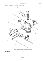
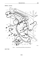
Disconnect leads (Figure 1, Item 1) and (Figure 1, Item 2) from warning light switch (Figure 1, Item 3).
2.
Remove tiedown strap (Figure 1, Item 26) from front main wiring harness (Figure 1, Item 20) and leads
(Figure
1,
Item
16) and (Figure 1, Item 19). Discard tiedown strap.
NOTE
Assistant will help with Step (3).
3.
Remove two screws (Figure 1, Item 29), washers (Figure 1, Item 30), lockwashers (Figure 1, Item 31), retainer
(Figure 1, Item 28), and grommet (Figure 1, Item 6) from firewall (Figure 1, Item 9). Discard lockwashers.
4.
Pull leads (Figure 1, Items 1 and 2) through hole in firewall (Figure 1, Item 9).
5.
Remove four screws (Figure 1, Item 4), clips (Figure 1, Item 5), and leads (Figure 1, Items 2, 8, 15, and 27)
from relay (Figure 1, Item 7).
6.
Remove two screws (Figure 1, Item 14), lockwashers (Figure 1, Item 13), lead (Figure 1, Item 27), and relay
(Figure 1, Item 7) from firewall (Figure 1, Item 9). Discard lockwashers.
7.
Disconnect lead (Figure 1, Item 16) from high-beam selector switch (Figure 1, Item 17).
8.
Disconnect leads (Figure 1, Item 10) and (Figure 1, Item 12) from circuit breaker (Figure 1, Item 11).
9.
Remove nut (Figure 1, Item 23), lockwasher (Figure 1, Item 22), and wires (Figure 1, Items 24 and 25) from
starter solenoid (Figure 1, Item 21). Discard lockwasher.
10.
Disconnect lead (Figure 1, Item 18) from connector (Figure 1, Item 19).
TM 9-2320-272-23-5
0804
0804-2
Back to Top


