TM-9-2320-272-24-1 - Page 248 of 1015
TM 9-2320-272-24-1
Table 2-3. Electrical Troubleshooting (Contd).
MALFUNCTION
TEST OR INSPECTION
CORRECTIVE ACTION
Step 8.
Connect lead 578 to air pressure switch A.
Step 9.
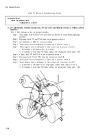
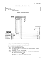
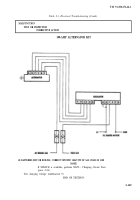
Disconnect wiring harness at failsafe warning control module.
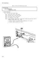
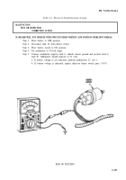
Step 10. Touch positive lead of multimeter to pin F (lead 578) and negative lead of multimeter to
frame ground.
a.
If continuity is present, go to step 11.
b.
If continuity is not present, replace lead 578 (para. 3-131).
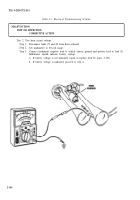
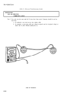
Step 11. Touch positive lead of multimeter to pin H (lead 57) and negative lead of multimeter to
frame ground.
a. If continuity is present, go to step 12.
b. If continuity is not present, replace lead 57 (para. 3-131).
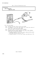
Step 12. Touch positive lead of multimeter to pin D (lead 350) and negative lead of multimeter to
frame ground.
a. If continuity is present, go to step 13.
b.
If continuity is not present, replace lead 350. (Refer to Digest Article, Engine
Overheating Warning System.)
Step 13. Ensure parking brake is engaged (TM 9-2320-272-10).
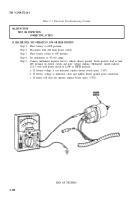
Step 14. Touch positive lead of multimeter to pin I (lead 584) and negative lead of multimeter to
frame ground.
If low air warning buzzer will not shut off, replace.
a.
If continuity is not present, replace lead 584 (para. 3-131).
END OF TESTING!
2-160
Back to Top


