TM-9-2320-272-24-1 - Page 438 of 1015
TM 9-2320-272-24-1
3-23. FUEL SELECTOR VALVE FLEX HOSE REPLACEMENT
THIS TASK COVERS:
a. Removal
b. Installation
INITIAL SETUP:
APPLICABLE MODELS
M929/A1/A2, M930/A1/A2, M931/A1/A2,
M932/A1/A2, M936/A1/A2
TOOLS
General mechanic’s tool kit (Appendix E, Item 1)
MATERIALS/PARTS
Cap and plug set (Appendix C, Item 14)
Antiseize tape (Appendix C, Item 72)
REFERENCES (TM)
TM 9-2320-272-10
TM 9-2320-272-24P
EQUIPMENT CONDITION
l
Parking brake set (TM 9-2320-272-10).
l
Hood raised and secured (TM 9-2320-272-10).
GENERAL SAFETY INSTRUCTIONS
Diesel fuel is flammable. Do not perform this
procedure near flames.
WARNING
Diesel fuel is highly flammable. Do not perform fuel system
procedures near flames. Injury to personnel may result.
a. Removal
NOTE
l
All hoses are disconnected the same.
l
All hoses must be disconnected from fuel lines first.
l
Have drainage container ready to catch fuel.
l
Plug all fuel lines using protective cap plugs.
l
Tag lines and fittings for installation.
1.
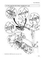
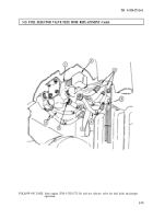
Disconnect six flex hoses (4) from four fuel lines (3) and two fuel line-to-hose adapters (5).
2.
Disconnect six flex hoses (4) from two valve ports (6) and four elbows (2) on selector valve (1).
b. Installation
NOTE
l
Male pipe threads must be wrapped with antiseize tape before
installation.
l
Remove protective cap plugs from fuel lines before installation.
1.
Connect six flex hoses (4) to two valve ports (6) and four elbows (2) on selector valve (1).
2.
Connect six flex hoses (4) to four fuel lines (3) and two fuel line-to-hose adapters (5).
3-74
Back to Top

