TM-9-2320-272-24-1 - Page 524 of 1015
3-55. AIR
TM 9-2320-272-24-1
THIS TASK COVERS:
a. Supply Tube Removal
b. Return Tube Removal
c. Inspection
d. Supply Tube Installation
e. Return Tube Installation
INITIAL SETUP:
APPLICABLE MODELS
M939/A1
TOOLS
General mechanic’s tool kit (Appendix E, Item 1)
MATERIALS/PARTS
Lockwasher (Appendix D, Item 349)
Four bushings (Appendix D, Item 21)
Antiseize tape (Appendix C, Item 72)
REFERENCES (TM)
TM 9-243
TM 9-2320-272-10
TM 9-2320-272-24P
EQUIPMENT CONDITION
• Parking brake set (TM 9-2320-272-10).
• Hood raised and secured (TM 9-2320-272-10).
• Cooling system drained (para. 3-63).
1.
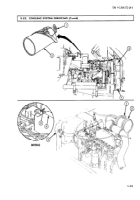
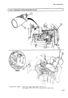
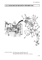
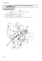
Loosen two flare nuts (4) and remove coolant supply tube (6) from water pump adapter (7) and air
compressor elbow (2), and slide nuts (4) to center of tube (6).
2.
Remove and discard two bushings (3) from tube (6).
3.
Remove water pump adapter (7) and air compressor elbow (2) from engine oil cooler (1) and air
compressor (5).
3-160
Back to Top

