TM-9-2320-272-24-1 - Page 532 of 1015
3-57. AIR
TM 9-2320-272-24-1
THIS TASK COVERS:
a. Removal
b. Cleaning and Inspection
c. Installation
INITIAL SETUP:
APPLICABLE MODELS
M939A2
TOOLS
REFERENCES (TM)
TM 9-2320-272-10
TM 9-2320-272-24P
General mechanic’s tool kit (Appendix E, Item 1)
EQUIPMENT CONDITION
MATERIALS/PARTS
• Hood raised and secured (TM 9-2320-272-10).
• Right splash shield removed (TM 9-2320-272-10).
Four seals (Appendix D, Item 625)
• Cooling system drained (para. 3-53).
Cap and plug-set (Appendix C, Item 14)
Antiseize tape (Appendix C, Item 72)
NOTE
When disconnecting water lines or hoses, plug ends and tag for
identification during installation.
1.
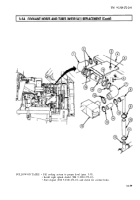
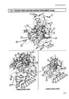
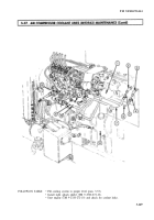
Disconnect two tubing nuts (10) and remove water outlet tube (7) and two seals (5) from air
compressor (11) and elbow (2) in cylinder head (1). Discard seals (5).
2.
Disconnect two tubing nuts (9) and remove water inlet tube (6) and two seals (4) from air
compressor (11) and elbow (3) in engine block (8). Discard seals (4).
3.
Remove elbow (2) from cylinder head (1) and elbow (3) from engine block (8).
1.
For general cleaning instructions, refer to para. 2-14.
2.
For general inspection instructions, refer to para. 2-15.
3.
Inspect tubes (6) and (7) for kinks, cracks, and bends.
4.
Replace all parts failing inspection.
NOTE
Male pipe threads must be wrapped with antiseize tape before
installation.
1.
Install elbow (3) on engine block (8) and elbow (2) on cylinder head (1).
2.
Install water inlet tube (6) and two new seals (4) on air compressor (11) and elbow (3) on engine
block (8).
3.
Install water outlet tube (7) and two new seals (5) on air compressor (11) and elbow (2) on cylinder
head (1).
3-168
Back to Top

