TM-9-2320-272-24-1 - Page 624 of 1015
3-90. SPEEDOMETER
TM 9-2320-272-24-1
NOTE
Pull driveshaft core out from driveshaft conduit 1-1/2 in. (38 mm)
to gain access to retaining washer.
13.
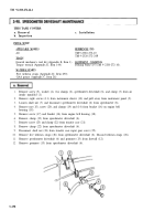
Remove retaining washer (3) and driveshaft core (1) from driveshaft (2).
1.
Inspect driveshaft (2) for cracks. Replace if cracked.
2.
Inspect driveshaft core (1) for breaks. Replace if broken.
1.
2.
3.
4.
5.
6.
7.
8.
9.
10.
NOTE
Apply thin coat of GM grease to driveshaft core.
Install driveshaft core (1) and retaining washer (3) on driveshaft (2).
Install grommet (10) with speedometer driveshaft (2) on firewall (9).
Connect shaft nut (21) to transfer case input gear cover (22).
Install speedometer driveshaft (2) and clamp (19) on transfer case (18) with screw (20). Tighten
screw (20) 40-65 lb-ft (54-88 N•m).
Install bracket (13) on engine bell housing (15) with screw (14). Tighten screw (14) 25-31 lb-ft
(34-42 N•m).
Install speedometer driveshaft (2), clamps (11) and (16) on bracket (13) with screw (17) and nut (12).
Install five new tiedown straps (23) on speedometer driveshaft (2).
Connect shaft nut (24) to speedometer (25).
Install instrument cluster (27) on instrument panel (26) with eight screws (28).
Install two clamps (5), speedometer driveshaft (2), clamp (6), washer (7), and screw (8) on air intake
manifold (4).
3-260
Back to Top

