TM-9-2320-272-24-1 - Page 846 of 1015
TM 9-2320-272-24-1
3-173. SPRING BRAKE VALVE MAINTENANCE
THIS TASK COVERS:
a. Removal
b. Adjustment
c. Installation
INITIAL SETUP:
APPLICABLE MODELS
REFERENCES (TM)
All
TM 9-2320-272-10
TOOLS
TM 9-2320-272-24P
General mechanic’s tool kit (Appendix E, Item 1)
EQUIPMENT CONDITION
MATERIALS/PARTS
Wheels chocked (TM 9-2320-272-10).
Two locknuts (Appendix D, Item 283)
Drain air reservoirs (TM 9-2320-272-10).
Gasket sealant (Appendix C, Item 30)
GENERAL SAFETY INSTRUCTIONS
Do not disconnect air lines before draining air
reservoirs.
1.
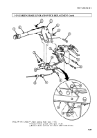
Release parking brake lever (8) (TM 9-2320-272-10).
WARNING
Do not disconnect air lines before draining air reservoirs. Small
parts under pressure may shoot out with high velocity, causing
injury to personnel.
NOTE
Tag air lines for installation.
2.
Disconnect three air lines (4) from adapter assemblies (3), (6), and (5).
3.
Remove adapter assemblies (3), (6), and (5) from valve body (1).
4.
Remove two locknuts (9), washers (10), screws (2), and valve body (1) from parking brake
bracket (7). Discard locknuts (9).
1.
Loosen setscrew (11) on valve lever (13) and position valve lever (13) parallel with valve body (1).
Tighten setscrew (11).
2.
Position valve body (1) on parking brake bracket (7). Valve lever (13) must be parallel with cab floor.
If not, repeat step 1.
1.
Install valve body (1) on parking brake bracket (7) with two screws (2), washers (10), and new
locknuts (9). Valve lever roller (12) must be aligned with parking brake lever (8).
2.
Lift up parking brake lever (8). Ensure parking brake lever (8) contacts valve lever roller (12)
properly and release parking brake lever (8).
3-482
Back to Top


