TM-9-2320-272-24-1 - Page 848 of 1015
TM 9-2320-272-24-1
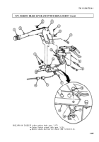
3-174. PARKING BRAKE LEVER AND SWITCH REPLACEMENT
THIS TASK COVERS:
a. Removal
b. Installation
APPLICABLE MODELS
REFERENCES (TM)
All
TM 9-2320-272-10
TOOLS
TM 9-2320-272-24P
General mechanic’s tool kit (Appendix E, Item 1)
EQUIPMENT CONDITION
MATERIALS/PARTS
Wheels chocked (TM 9-2320-272-10).
Battery ground cable disconnected (para. 3-126).
Cotter pin (Appendix D, Item 46)
Four locknuts (Appendix D, Item 291)
1.
Release parking brake lever (2) (TM 9-2320-272-101.
2.
Turn adjusting cap (1) on parking brake lever (2) completely out.
3.
Remove cotter pin (5), washer (6), and clevis pin (7) from cable clevis (14). Discard cotter pin (6).
4.
Remove three locknuts (3), screws (9), spacer washer (10), and spring parking brake valve and
bracket (8) from parking brake housing (4) and brackets (13). Carefully set valve and bracket (8)
aside. Discard locknuts (3).
5.
Remove parking brake housing (4) from parking brake brackets (13).
6.
Disconnect wire (11) from wire (12) under vehicle cab.
NOTE
Assistant will help with step 7.
7.
Remove locknut (18), wire (17), and screw (16) from cab floor (19). Discard locknut (18).
8.
Remove parking brake switch (15) from brackets (13).
NOTE
Assistant will help with step 1.
1.
Install wire (17) on cab floor (19) with screw (16) and new locknut (18).
2.
Connect wire (11) to wire (12).
3.
Install parking brake housing (4), spring parking brake valve and bracket (8), and parking brake
switch (16) on brackets (13) with three screws (9), spacer washer (10), and three new locknuts (3).
4.
Install clevis pin (7) on cable clevis (14) with washer (6) and new cotter pin (5).
INITIAL SETUP
3-484
Back to Top


