TM-9-2320-272-24-1 - Page 934 of 1015
TM 9-2320-272-24-1
3-204. EMERGENCY SPRING BRAKE (SUPPLY TANK) AIR RESERVOIR REPLACEMENT
THIS TASK COVERS:
a. Removal
b. Installation
INITIAL SETUP:
APPLICABLE MODELS
All
TOOLS
General mechanic’s tool kit (Appendix E, Item 1)
MATERIALS/PARTS
Four locknuts (Appendix D, Item 276)
Antiseize tape (Appendix C, Item 72)
REFERENCES (TM)
TM 9-2320-272-10
TM 9-2320-272-24P
EQUIPMENT CONDITION
l
Parking brake set (TM 9-2320-272-10).
l
Air reservoirs drained (TM 9-2320-272-10).
l
Toolbox and step removed (para. 3-302).
GENERAL SAFETY INSTRUCTIONS
l
Do not disconnect air lines before draining air
reservoirs.
l
Do not touch hot exhaust system components with
bare hands.
WARNING
l
Do not disconnect air lines before draining air reservoirs. Small
parts under pressure may shoot out with high velocity, causing
injury to personnel.
l
Do not touch hot exhaust system components with bare hands.
Injury to personnel may result.
a. Removal
NOTE
l
Spring brake reservoir is located on the left frame rail next to
air cleaner.
l
Tag air lines for installation.
1.
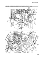
Disconnect air lines (5), (6), and (7) from elbows (10), (8), and (9).
2.
Remove four locknuts (4), washers (3), two U-bolts (11), and emergency reservoir (1) from two
support brackets (2). Discard locknuts (4).
b. Installation
NOTE
l
If installing new reservoir, use old reservoir fittings. Wrap all
male pipe threads with antiseize tape before installation.
l
When installing emergency tank, ensure emergency tank
drainvalve port faces downward and toward front of vehicle.
1.
Install emergency reservoir (1) on two support brackets (2) with two U-bolts (11), four washers (3),
and new locknuts (4).
2.
Connect air lines (5), (6), and (7) to elbows (10), (8), and (9).
3-570
Back to Top


