TM-9-2320-272-24-2 - Page 314 of 991
TM 9-2320-272-24-2
3-376. SIDE AND REAR DOOR BLACKOUT LIGHT SWITCH MAINTENANCE
THIS TASK COVERS:
a. Removal
b. Installation
c. Adjustment
APPLICABLE MODEL
REFERENCES (TM)
M934/A1/A2
TM 9-2320-272-10
TOOLS
TM 9-2320-272-24P
General mechanic’s tool kit (Appendix E, Item 1)
EQUIPMENT CONDITION
MATERIALS/PARTS
Parking brake set (TM 9-2320-272-10)
Main power switch off (TM 9-2320-272-10).
Solder (Appendix C, Item 70)
Van body side panel fully expanded and secured
(TM 9-2320-272-10).
1.
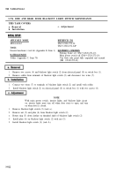
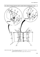
Remove two screws (4) and blackout light switch (2) from electrical panel (8) or switch box (1).
2.
Remove solder from terminals of blackout light switch (2) and disconnect two wires (7).
1.
Connect two wires (7) to terminals of blackout light switch (2) and install with solder.
2.
Install blackout light switch (2) on electrical panel (8) or switch box (1) with two screws (4).
1.
Remove blackout light switch (2) (task a.).
2.
Remove nut (5) and plate (6) from blackout light switch (2).
3.
Rotate ring (3) down farther on threaded shaft of blackout light switch (2).
4.
Install plate (6) on blackout light switch (2) with nut (5).
5.
Install blackout light switch (2) (task b.).
NOTE
With main power switch, interior lights, and blackout light circuit
on, interior lights must turn off when door starts to open, and turn
on when door is closed.
3-922
Back to Top


