TM-9-2320-272-24-2 - Page 308 of 991
TM 9-2320-272-24-2
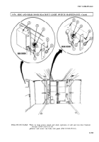
3-373. BLACKOUT LIGHT SWITCH AND 110-VOLT RECEPTACLE REPLACEMENT
THIS TASK COVERS:
a Removal
b. Installation
APPLICABLE MODELS
REFERENCES (TM)
M934/A1/A2
TM 9-2320-272- 10
TOOLS
TM 9-2320-272-24P
General mechanic’s tool kit (Appendix E, Item 1)
EQUIPMENT CONDITION
Parking brake set TM 9-2820-272-10).
Auxiliary A/C power source disconneted
(TM 9-2320-272-10).
1.
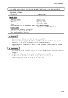
Remove three screws (7) and cover plate (6) from box (1).
2.
Remove two screws (8) and pull switch (9) away from box (1).
3.
Remove two screws (5) and pull receptacle (4) away from box (1).
NOTE
Tag all leads for installation.
4.
Remove five screws (3) and leads (2) from pull switch (9).
5.
Remove five screws (3) and leads (2) from receptacle (4).
1.
Install five leads (2) on receptacle (4) with five screws (3).
2.
Install five leads (2) on pull switch (9) with five screws (3).
3.
Install receptacle (4) on box (1) with two screws (5).
4.
Install pull switch (9) on box (1) with two screws (8).
5.
Install cover plate (6) on box (1) with three screws (7).
3-916
Back to Top

