TM-9-2320-272-24-2 - Page 882 of 991
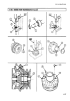
4-29. WATER
TM 9-2320-272-24-2
THIS TASK COVERS:
a. Removal
b. Disassembly
c. Cleaning and Inspection
d. Assembly
e. Installation
INITIAL SETUP:
APPLICABLE MODELS
M939/A1
TOOLS
General mechanic’s tool kit (Appendix E, Item 1)
Mechanical wedge puller (Appendix E, Item 101)
Outside micrometer (Appendix E, Item 80)
Snap gauge (Appendix E, Item 123)
Torque wrench (Appendix E, Item 146)
Arbor press
Wire brush
Mandrel driver
MATERIALS/PARTS
Two lockwashers (Appendix D, Item 350)
Gasket (Appendix D, Item 153)
Water pump seal assembly (Appendix D,
Item 635)
Snapring (Appendix D, Item 660)
O-ring (Appendix D, Item 425)
Snapring (Appendix D, Item 662)
Eight lockwashers (Appendix D, Item 349)
Two relief fittings (Appendix D, Item 532)
GAA grease (Appendix C, Item 28)
Detergent (Appendix C, Item 27)
REFERENCES (TM)
TM 9-2320-272-10
TM 9-2320-272-24P
TM 9-214
EQUIPMENT CONDITION
Cooling system drained (para. 3-53).
Fan drive clutch removed (para. 3-75).
Water pump drivebelt removed (para. 3-67).
Alternator adjusting link removed (para. 3-79).
GENERAL SAFETY INSTRUCTIONS
When cleaning with compressed air, wear eyeshields
and ensure source pressure does not exceed 30 psi
(207 kPa).
1.
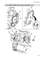
Remove screw (2), lockwasher (3), hose clamp (4), and spacer (5) from engine bracket (6). Discard
lockwasher (3).
2.
Remove screw (1), lockwasher (12), and washer (11) from engine bracket (6). Discard lockwasher (12).
3.
Remove six screws (9) and lockwashers (8) from support bracket (7). Discard lockwashers (8).
4.
Remove support bracket (7) from engine block (10).
5.
Remove water pump body (16) and O-ring (15) from water pump support (14). Discard O-ring (15).
6.
Remove two screws (17) and lockwashers (18) from engine block (10). Discard lockwashers (18).
7.
Remove water pump support (14) and gasket (13) from engine block (10). Discard gasket (13).
4-200
Back to Top


