TM-9-2320-272-24-2 - Page 934 of 991
TM 9-2320-272-24-2
4-33. VALVE AND INJECTOR ADJUSTMENT (DIAL INDICATOR METHOD) (Contd)
Table 4-2. Engine Firing Order.
Right hand rotation
1-5-3-6-2-4
NOTE
Preceding steps cover injector adjustments for No. 3 cylinder.
Follow table 4-3 for the remaining five injectors.
Table 4-3. Injector and Valve Set Position.
ROTATION
PULLEY
DIRECTION
POSITION
Start
1-6 VS
3
5
Advance to
2-5 VS
6
3
Advance to
3-4 vs
2
6
Advance to
1-6 VS
4
2
Advance to
2-5 VS
1
4
Advance to
3-4 VS
5
1
ADJUST CYLINDER
INJECTOR
VALVE
NOTE:
Two complete revolutions of pulley are required to adjust all injectors
and valves.
Table 4-4. Uniform Plunger Travel Adjustment Limits.
OIL
TEMP.
INJECTOR PLUNGER TRAVEL
VALVE CLEARANCE
ADJUST VALVE
RECHECK LIMIT
INTAKE
EXHAUST
IN.
(MM)
Aluminum Rocker Housing
Cold 0.170
(4.32)
IN.
(MM)
IN.
(MM)
IN.
(MM)
0.169-0.171
(4.29-4.34)
0.011
(0.28)
0.023
(0.58)
12.
13.
14.
15.
16.
17.
18.
19.
4-252
NOTE
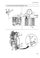
With engine position at 1-6 VS mark, No. 3 cylinder has been
adjusted, and now valves in No. 5 cylinder must be adjusted.
Loosen locknut (1) on intake rocker lever (4) of No. 5 cylinder (3) and back out adjusting screw (2).
Insert feeler gauge between rocker lever (4) nose and crosshead. See table 4-4 for valve clearance
settings.
Slowly turn down adjusting screw (2) with screwdriver until rocker lever (4) nose touches feeler gauge.
Check clearance by removing and inserting feeler gauge. There will be a slight drag on gauge when
clearance is correct.
Ensure adjusting screw (2) does not move by holding it firmly in position while tightening
locknut (1) 40-45 lb-ft (54-61 N•m).
Repeat steps 12 through 16 to adjust exhaust rocker lever (5). See table 4-4 for valve clearance
settings.
Advance pulley (6) so pointer (8) is at next timing mark (7) and perform injector and valve
adjustments indicated in tables 4-2 and 4-3.
Advance pulley (6) to next timing mark (7) after each set of injector and valve adjustments until all
timing is completed.
Back to Top


