TM-9-2320-272-24-3 - Page 286 of 799
TM 9-2320-272-24-3
4-98. STEERING KNUCKLE MAINTENANCE
THIS TASK COVERS:
a.
Removal
c.
Installation
b.
Cleaning and Inspection
d. End Play Test
INITIAL SETUP:
APPLICABLE MODELS
All
TOOLS
General mechanic’s tool kit (Appendix E, Item 1)
Inside micrometer (Appendix E, Item 82)
Burnishing tool (Appendix E, Item 22)
Torque wrench (Appendix E, Item 145)
Dial indicator (Appendix E, Item 36)
Jack stand
Arbor press
MATERIALS/PARTS
Lockwire, 40 in. (Appendix D, Item 419)
Three cotter pins (Appendix D, Item 85)
Stop screw (Appendix D, Item 679)
Jamnut (Appendix D, Item 264)
Sleeve bearing (Appendix D, Item 657)
Four lockwashers (Appendix D, Item 399)
GAA grease (Appendix C, Item 28)
Sealing compound (Appendix C, Item 30)
REFERENCES (TM)
LO 9-2310-272-12
TM 9-2320-272-10
TM 9-2320-272-24P
EQUIPMENT CONDITION
Front axle shaft removed (para. 3-154).
a. Removal
NOTE
l
Perform step 1 for left steering knuckle only.
l
Perform step 2 for right steering knuckle only.
1.
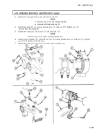
Remove cotter pin (10), nut (9), and drag link (8) from steering knuckle arm (3). Discard cotter
pin (10).
2.
Remove cotter pin (28), nut (27), and socket assembly (25) with ball stud (26) from steering knuckle
arm (3). Discard cotter pin (28).
3.
Remove cotter pin (13), nut (14), and tie rod (15) from steering knuckle (1). Discard cotter pin (13).
4.
Remove four nuts (6), lockwashers (5), bushings (4), and steering knuckle arm (3) from steering
knuckle (1). Discard lockwashers (5).
5.
Remove lubrication fitting (7) from steering knuckle arm (3).
6.
Insert two puller screws into screw holes (12) of upper sleeve (2), and remove from steering
knuckle (1).
7.
Remove spacer (11) from upper sleeve (2).
8.
Remove two screws (24) and washers (23) from seal guard (22) and steering knuckle (1).
9.
Remove grease fitting (19), four screws (20), washers (21), lower plate (18), and seal guard (22) from
steering knuckle (1).
10.
Insert two puller screws into screw holes (16) of lower sleeve (17), and remove from steering
knuckle (1).
11.
Remove lockwire (31) and twelve screws (29) from dust seal plate (30) and steering knuckle (1).
Discard lockwire (31).
4-550
Back to Top

