TM-9-2320-272-24-3 - Page 294 of 799
TM 9-2320-272-24-3
4-99. FRONT AXLE REPLACEMENT
THIS TASK COVERS:
a. Removal
b. Installation
INITIAL SETUP:
APPLICABLE MODELS
All
TOOLS
General mechanic’s tool kit (Appendix E, Item 1)
Torque wrench (Appendix E, Item 145)
Four jack stands
Hydraulic jack
MATERIALS/PARTS
Two locknuts (Appendix D, Item 286)
Cotter pin (Appendix D, Item 49)
Eight lockwashers (Appendix D, Item 362)
Eight locknuts (Appendix D, Item 291)
Cotter pin (Appendix D, Item 85)
Lubricating oil (Appendix C, Item 50)
Antiseize tape (Appendix C, Item 72)
REFERENCES (TM)
TM 9-2320-272-10
TM 9-2320-272-24P
EQUIPMENT CONDITION
l
Parking brake set (TM 9-2320-272-10)
l
Rear wheels chocked (TM 9-2320-272-10).
l
Air reservoirs drained (TM 9-2320-272-10).
l
Front wheels removed (para. 3-218 or 3-219).
GENERAL SAFETY INSTRUCTIONS
l
Do not attempt to support weight of vehicle on
hydraulic jack.
l
Do not disconnect air lines before draining air
reservoirs.
WARNING
Weight of vehicle must remain supported on jack stands at all
times. Do not attempt to support weight of vehicle on hydraulic
jack. Injury to personnel may result if jack fails.
1.
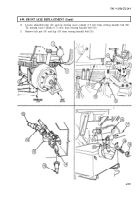
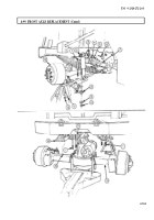
Position hydraulic jack under front axle differential housing (3) and raise vehicle.
2.
Position two jack stands under springs (2), ahead of left and right spring hangers (1).
NOTE
Do not fully lower hydraulic jack.
3.
Lower hydraulic jack enough for springs (2) to rest on jack stands.
WARNING
Do not disconnect air lines before draining air reservoirs. Small
parts under pressure may shoot out with high velocity, causing
injury to personnel.
4.
Disconnect primary line (4) and vent line (6) from left and right service brake chambers (8).
5.
Remove adapter (5) and elbow (7) from left and right service brake chambers (8).
NOTE
l
Perform step 6 for M939A2 series vehicles.
l
Perform step 7 for left side of vehicle.
l
Perform steps 8 through 11 for right side of vehicle.
6.
Disconnect two air lines (13) from adapters (14) on relief safety valve (15).
7.
Remove cotter pin (10), nut (9), and drag link (12) from steering knuckle arm (11). Discard cotter
pin (10). Tie drag link (12) away from steering knuckle arm (11).
8.
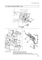
Remove cotter pin (16) from steering assist cylinder (17). Discard cotter pin (16).
9.
Bend tabs of clip (18) away from felt pad (19) and steering knuckle ball (20).
4-558
Back to Top


