TM-9-2320-272-24-4 - Page 202 of 836
TM 9-2320-272-24-4
5-29. CRANKSHAFT AND GEAR MAINTENANCE
THIS TASK COVERS:
a.
Check End Play
d.
Cleaning and Inspection
b. Removal
e.
Assembly
c.
Disassembly
f.
Installation
INITIAL SETUP:
APPLICABLE MODELS
REFERENCES (TM)
M939A2
TM 9-2320-272-24P
SPECIAL TOOLS
EQUIPMENT CONDITION
Torque angle gauge (Appendix E, Item 141)
Fuel injectors removed (para. 4-55).
TOOLS
Oil pan and suction tube removed (para. 4-47).
General mechanic’s tool kit (Appendix E, Item 1)
Front gearcase housing removed (para. 4-46).
Flexplate and flywheel housing removed
Heavy duty gear puller (Appendix E, Item 102)
(para. 4-43).
Dial indicator (Appendix E, Item 36)
Rear cover and oil seal removed (para. 4-44).
Torque wrench (Appendix E, Item 144)
Feeler gauge
GENERAL SAFETY INSTRUCTIONS
Prybar
Drycleaning solvent is flammable and toxic. Do
Soft-head hammer
not use near open flame.
Nylon brush
Keep fire extinguisher nearby when using
MATERIALS/PARTS
drycleaning solvent.
Eyeshields must be worn when cleaning with
Dowel pin (Appendix D, Item 99)
compressed air. Compressed air source will not
Crankshaft main bearing set
(Appendix D, Item 87)
exceed 30 psi (207 kPa).
Drycleaning solvent (Appendix C, Item 71)
GAA grease (Appendix C, Item 28)
Lubricating oil (Appendix C, Item 50)
Plastigage (Appendix C, Item 55)
Crocus cloth (Appendix C, Item 20)
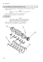
a. Check End Play
1.
Position engine block (2) so crankshaft (1) is facing upward.
2.
Install dial indicator on engine block (2) with plunger on face of crankshaft gear (3).
3.
Move crankshaft (1) towards rear of engine block (2) using prybar.
4.
Set dial indicator to zero.
5.
Move crankshaft (1) toward front of engine block (2) using prybar. Record dial indicator reading.
6.
Replace thrust bearing in subtasks b and f if crankshaft (1) end play is not between 0.006-0.013 in.
(0.152-0.330 mm).
5-196
Back to Top


