TM-9-2320-272-24-4 - Page 230 of 836
TM 9-2320-272-24-4
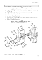
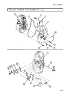
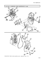
5-33. MANIFOLD PRESSURE COMPENSATOR MAINTENANCE
THIS TASK COVERS:
a. Removal
d. Assembly
b. Disassembly
e. Installation
c. Cleaning and Inspection
INITIAL SETUP:
APPLICABLE MODELS
REFERENCES (TM)
M939A2
TM 9-2320-272-24P
TOOLS
EQUIPMENT CONDITION
General mechanic’s tool kit (Appendix E, Item 1)
Fuel injection pump pretest performed (para. 5-32).
MATERIALS/PARTS
Manifold pressure compensator maintenance
kit (Appendix D, Item 423)
Silicone adhesive (Appendix C, Item 3)
a. Removal
1.
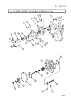
Remove safety wire (1) from screw (24) and protective cap (2). Discard safety wire (1).
NOTE
2.
3.
4.
5.
6.
7.
8.
It may be necessary to cut a slot on breakoff screws for removal.
Remove breakoff screw (22), screw (24), lockwashers (21) and (23), protective cap (2), and pull-
stop (3) from pull-stop cover (16). Discard breakoff screw (22) and lockwashers (21) and (23).
Remove O-ring (4) from pull-stop (3). Discard O-ring (4).
Remove nuts (20) and (19) from stop bolt (12).
Remove three screws (18) and lockwashers (17) from pull-stop cover (16). Discard lockwashers (17).
Remove breakoff screw (5), lockwasher (6), and pull-stop cover (16) from manifold pressure
compensator (7). Discard breakoff screw (5) and lockwasher (6).
Remove three screws (8), lockwashers (9), and washers (10) from manifold pressure compensator (7).
Discard lockwashers (9).
Remove breakoff screw (15), lockwasher (14), washer (13), and manifold pressure compensator (7)
from governor cover (11). Discard breakoff screw (15) and lockwasher (14).
b. Disassembly
1.
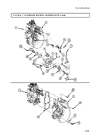
Remove cotter pin (28), washer (27), and lever (26) from stop bolt (12). Discard cotter pin (28).
2.
Remove stop bolt (12) and spring (29) from manifold pressure compensator (7).
3.
Remove round nut (34), washer (33), washer plate (32), diaphragm (31), and washer plate (30) from
stop bolt (12). Discard diaphragm (31).
4.
Remove O-ring (25) from manifold pressure compensator (7). Discard O-ring (25).
5-224
Back to Top


