TM-9-2320-272-24-4 - Page 244 of 836
TM 9-2320-272-24-4
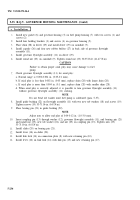
5-35. R.Q.V. GOVERNOR HOUSING MAINTENANCE (Contd)
f. Adjustment
1.
2.
3.
4.
5.
6.
7.
8.
9.
10.
11.
12.
13.
14.
15.
16.
NOTE
Distance is obtained by the measured distance plus the thickness
of straightedge minus half the thickness of slider.
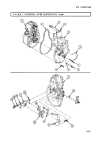
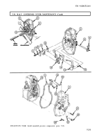
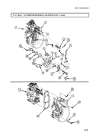
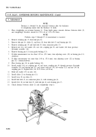
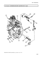
Place straightedge on governor housing (1). Using depth gauge, measure distance between slider (2)
and straightedge. Distance should be 1.39-1.40 in. (35.3-35.6 mm).
NOTE
Perform steps 2 through 15 if measurement is incorrect.
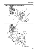
Remove retaining pin (7) from link pin (6).
Remove link pin (6). slider (2), and lever (8) from link fork (5) and bearing pin (11).
Remove retaining pin (4) and link fork (5) from connection plate (3).
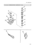
Remove nut (14), tab washer (15), nut (14), coupling pin (9), and washer (10) from governor
flyweight assembly (16).
Remove bearing pin (11) from guide bushing (13).
If slider measurement was less than 1.39 in. (35.3 mm), turn adjusting screw (12) in bearing pin (11)
clockwise.
If slider measurement was more than 1.40 in. (35.6 mm), turn adjusting screw (12) in bearing
pin (11) counterclockwise.
Place bearing pin (11) in guide bushing (13).
Install washer (10) on coupling pin (9) and insert coupling pin (9) through governor flyweight
assembly (16) and bearing pin (11) and secure with nut (14), tab washer (15), and nut (14) on
coupling pin (9). Tighten nuts (14) 53-71 lb-in. (6-8 N·m).
Bend tab washer (15) on nuts (14).
Install slider (2) on bearing pin (11).
Install lever (8) on slider (2).
Install link fork (5) on connection plate (3) with retaining pin (4).
Install lever (8) on link fork (5) with link pin (6) and retaining pin (7).
Check distance between slider (2) and straightedge (step 1).
5-238
Back to Top

