TM-9-2320-272-24-4 - Page 504 of 836
TM 9-2320-272-24-4
5-74. REAR WALL INTERIOR PANELS REPLACEMENT
THIS TASK COVERS:
a. Removal
b. Installation
INITIAL SETUP:
APPLICABLE MODELS
EQUIPMENT CONDlTlON
M934/A1/A2
l
l
TOOLS
l
General mechanic’s tool kit (Appendix E, Item 1)
l
MATERIALS/PARTS
l
Sealing compound (Appendix C, Item 67)
l
REFERENCES (TM)
l
TM 9-2320-272-10
l
TM 9-2320-272-24P
l
Parking brake set (TM 9-2320-272-10).
Rear doors opened (TM 9-2320-272-10).
Van body sides fully expanded and secured
(TM 9-2320-272-10).
Inside telephone jack post removed (para. 3-374).
Blackout light switch removed (para. 3-373).
Fire extinguisher bracket removed (para. 3-416).
Electrical load center removed (para. 4-161).
Electrical junction box removed (para. 4-163).
Converter outlet box removed (para. 4-169).
Heater thermostat removed (para. 4-165).
SPECIAL ENVIRONMENTAL CONDlTlONS
Vehicle must be on a level surface.
NOTE
l
Rear wall exterior panels are not serviceable and if damaged
are replaced as a unit with rear wall assembly.
l
Left and right rear wall interior panels are replaced the same
way. This procedure is for the left rear wall interior panel.
NOTE
Assistant will help with step 2.
1.
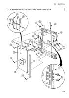
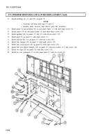
Remove thirteen screws (4) and molding (1) from panel (2) and header (3).
2.
Remove twenty-two screws (5) and panel (2) from header (3).
3.
Remove eight screws (9) and two gussets (8) from skin (7) and underframe (6).
NOTE
l
Apply sealing compound to exterior joints prior to installation.
l
Assistant will help with step 2.
1.
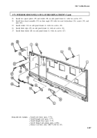
Install two gussets (8) on skin (7) and underframe (6) with eight screws (9).
2.
Install panel (2) on header (3) with twenty-two screws (5).
3.
Install molding (1) on panel (2) and header (3) with thirteen screws (4).
5-498
Back to Top

