TM-9-2320-272-24-4 - Page 8 of 836
TM 9-2320-272-24-4
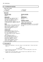
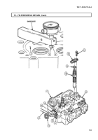
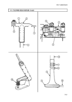
5-3. CYLINDER HEAD REPAIR
THIS TASK COVERS:
a. Disassembly
b. Cleaning
c. Inspection
d. Assembly
INITIAL SETUP:
APPLICABLE MODELS
PERSONNEL REQUIRED
M939/Al
TWO
SPECIAL TOOLS
Head holding future (Appendix E, Item 7)
Cleaning brush (Appendix E, Item 28)
Valve guide arbor (Appendix E, Item 153)
Gauge block (Appendix E, Item 52)
Crosshead guide puller (Appendix E, Item 106)
Crosshead guide spacer (Appendix E, Item 33)
REFERENCES (TM)
TM 9-2320-272-24P
TM 9-247
EQUIPMENT CONDlTlON
Cylinder head removed (para. 4-12).
TOOLS
General mechanic’s tool kit (Appendix E, Item 1)
Outside micrometer (Appendix E, Item 80)
Depth micrometer (Appendix E, Item 81)
Torque wrench (Appendix D, Item 145)
Soft-faced hammer
GENERAL SAFETY INSTRUCTIONS
When cleaning with compressed air, wear eyeshields
and ensure source pressure does not exceed 30 psi
(207 kPa).
MATERIALS/PARTS
Six freeze plugs (Appendix D, Item 133)
Sixteen half-keepers (Appendix D, Item 253)
Two O-rings (Appendix D, Item 438)
Two screw-assembled lockwashers (Appendix D,
Item 578)
Gasket (Appendix D, Item 94)
Freeze plug (Appendix D, Item 132)
Two freeze plugs (Appendix D, Item 134)
Lubricating oil (Appendix C, Item 50)
Prussian blue (Appendix C, Item 54)
Sealing compound (Appendix C, Item 61)
Antiseize tape (Appendix C, Item 72)
Crocus cloth (Appendix C, Item 20)
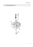
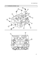
a. Disassembly
1.
Remove sixteen half-keepers (1) from valve springs (3) and cylinder head (7). Discard sixteen half-
keepers (1).
NOTE
Tag springs for installation
2.
Remove eight upper spring guides (2), valve springs (3), and lower spring guides (4) from valve
guide (5) and cylinder head (7).
3.
Tap eight valve (6) stems down lightly to loosen and remove from cylinder head (7). Place on
numbered valve board and hold for inspection.
5-2
Back to Top

