TM-9-2320-272-24-4 - Page 12 of 836
TM 9-2320-272-24-4
5-3. CYLINDER HEAD REPAIR (Contd)
b. Cleaning
Clean all cylinder head (1) components (TM 9-247).
c. Inspection
1.
2.
3.
4.
5.
6.
7.
8.
9.
10.
11.
12.
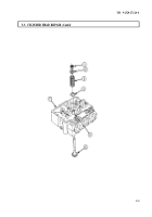
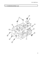
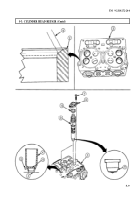
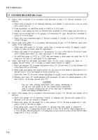
Install four pipe plugs (11) in front and rear face of cylinder head (1).
NOTE
Apply sealing compound to outer diameter of freeze plugs before
installation.
Install new freeze plug (10) in front face of cylinder head (1).
Install two new freeze plugs (2) in cylinder head (1).
Install two new freeze plugs (7) in front and rear face of cylinder head (1).
Install four new freeze plugs (9) in exhaust ports (8) on cylinder head (1).
Install two new O-rings (5), plate (4), and two new screw-assembled lockwashers (3) on fuel
crossover connection (6) in cylinder head (1).
CAUTION
Do not use sander to polish cylinder heads. Serious damage to
gasket sealing surfaces can result.
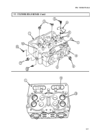
Clean cylinder head mating surfaces (12) lightly enough to remove all gasket remains and carbon
deposits. Inspect in accordance with instructions in para. 5-25.
NOTE
Instructions for use of portable magnetic tester are included with
the tester.
Inspect valve seats (13) and injector ports (14) on cylinder head (1) for cracks. If cracks are found,
replace cylinder head (1).
NOTE
The following examples of cylinder head defects are provided to
assist in determining causes of failures.
Check cylinder head valve seats (13) and injector ports (14) for hot spots and correct probable causes.
If this condition exists, probable causes are overheating, loss of coolant, coolant flow stoppage, over-
fueling, tight injector holddowns, incorrect injector sleeve installation, defective casting, hot
shutdowns, and incorrect insert fittings. If hot spots are found, replace cylinder head (1).
Check cylinder head (1) and water passage holes (15) for pits and scratches. If pits and scratches are
less than .003 in. (0.08 mm), remove with crocus cloth. If pits and scratches are more than 0.003 in.
(0.08 mm) deep in the area 0.-625-0.156 in. (1.59-3.97 mm) from edge of water passage hole (15),
replace cylinder head (1).
Check cylinder head surfaces (12) for warped surfaces. If warped surface exceeds 0.002 in. (0.05 mm),
replace cylinder head (1).
Check cylinder head (1) for required thickness. Cylinder head (1) must measure 4.340 in. (110.24
mm) thick. If less than 4.340 in. (110.24 mm) thick, replace cylinder head (1).
5-6
Back to Top

