TM-9-2320-272-24-4 - Page 20 of 836
TM 9-2320-272-24-4
5-3. CYLINDER HEAD REPAIR (Contd)
d. Assembly
NOTE
Use repaired and inspection-approved cylinder heads only.
1.
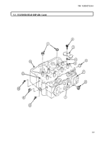
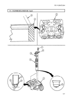
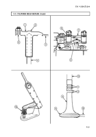
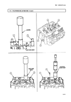
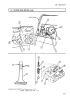
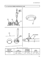
Replace worn valve guides (3). Drive valve guides (3) from underside of cylinder head (2) with
hammer and punch.
2.
Using arbor press, mandrel, and valve guide arbor, install new valve guides (3).
3.
Using crosshead guide puller, remove defective crosshead guides (6) from cylinder head (2).
4.
Thoroughly clean crosshead guide (9) holes.
5.
Check crosshead guide (6) height. Assembled height must be 1.860-1.880 in. (47.24-47.75 mm).
To install intake and exhaust valves, position cylinder head on
intake port face. Use wooden surface, workbench, or protective
surface to prevent damage. Bench must be clean.
Be sure to install valves in original locations as numbered in
step 3.
Ensure cylinder head is clean
6.
Dip valve stem (4) in clean engine oil.
7.
Install valve stems (4) through valve guides (3) from face side (5) of cylinder head (2). Ensure valve
heads are correctly seated on valve seats (1).
8.
Carefully position cylinder head (2) face down on workbench after all valves are installed so valve
springs can be installed.
CAUTION
Two differently-designed valve spring guides have been used in
NHC-250 series engines. Part number 128879 spring guide
cannot be used with 211999 valve spring. Number 170296
spring guide can be used with either valve spring.
Reground valve heads seat deeper in cylinder head, causing
valve stem to protrude farther above valve guide. This allows
valve spring to extend beyond length limits of 2.250 in. (57.150
mm), and causes weak spring action. Use spacers up to 0.0625
in. (15.875 mm) to reduce valve spring to proper height.
5-14
Back to Top

