TM-9-2320-272-24-4 - Page 22 of 836
TM 9-2320-272-24-4
5-3. CYLINDER HEAD REPAIR (Contd)
9.
10.
11.
12.
13.
NOTE
A maximum of two 0.03125 in. (0.794 mm) spacers may be used
under lower spring guide when cylinder head has been resurfaced
and valve seat insert has been refaced. Do not use spacers to
compensate for weak springs.
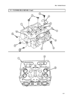
Place eight lower spring guides (18) over valve guides (16) and seat to cylinder head (1).
NOTE
Do not mix intake and exhaust springs. Intake springs are taller.
Place eight valve springs (15) on lower spring guides (18).
Place eight upper spring guides (14) on top of springs (15) and over stem end of valve (8). Compress
spring compressor until keeper grooves (12)on valve (8) are exposed.
Install new keepers (13) into valve grooves (12) and slowly release spring compressor. Repeat this
step until all valves (8) are locked by keepers (13).
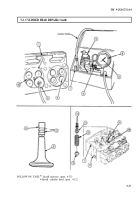
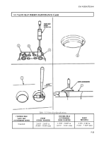
Using vacuum tester, test intake and exhaust valves (8) for proper seating.
a.
b.
C.
d.
e.
f.
g.
h.
i.
j.
k.
l.
m.
n.
NOTE
Valves and valve seats must be dry.
Grease can be applied to O-ring on vacuum cup for better seal.
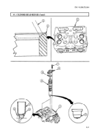
Select correct size vacuum cup (9) for size valves (8) being tested.
Hold vacuum cup (9) over head of valve (8) and seat flat on cylinder head surface (2)
surrounding valve (8).
Turn tester shutoff valve (6) to open position and hold pushbutton (7) down to operate vacuum
pump (4).
Operate tester shutoff valve (6) until indicator hand (5) on vacuum gauge (4) stops climbing
between 18-25 in. (457-635 mm) of mercury. Close tester shutoff valve (7) and release
pushbutton (8).
Begin timing as soon as hand (5) reaches 18 in. of mercury on gauge (4).
Stop timing as soon as indicator hand (5) reaches 8 in. (20.32 cm) of mercury. If time is less
than ten seconds, valve (8) seating is not satisfactory
Tap valve stem end with soft-faced hammer and retest by repeating steps a through f.
If valve seating is unsatisfactory, proceed to step i.
Check for loose connections on tester.
Operate vacuum pump (3) with suction cup (9) against a clear glass window.
Check indicator hand (5) for movement. If indicator hand (5) moves, there is leakage in the
tester.
Tighten connections and retest valves (8).
Repeat steps b through 1.
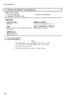
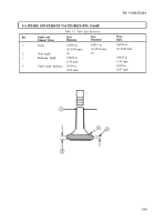
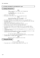
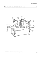
If test fails, regrind valves before retesting (para. 5-4).
5-16
Back to Top

