TM-9-2320-279-20-2 - Page 100 of 938
TM 9-2320-279-20-2
Brake and Air System Maintenance Instructions (Cont)
11-7.
BRAKE INSPECTION ADJUSTMENT (CONT).
(3)
(4)
(5)
(6)
(7)
(8)
(9)
NOTE
Use 80 to 90 psi (552 to 620 kPa) air
pressure for inspection.
Front brake chamber is shown. Rear
brake chamber is measured in the
same manner.
Some vehicles have manually
adjusted slack adjusters. Others
have automatic slack adjusters.
Perform steps (3) through (6) for
manually adjusted slack adjusters.
Perform steps (7), (8), and (9) for
automatic slack adjusters.
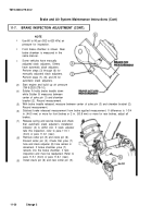
Start engine and build up air pressure
(TM 9-2320-279-10).
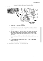
Soldier A holds brake treadle down
while Soldier B measures between
center of yoke pin (1) and chamber
bracket (2). Record measurement.
With brake treadle released, measure between center of yoke pin (3) and chamber bracket (2).
Record measurement.
Subtract brake released measurement from brake applied measurement. If difference is 1-3/4
in. (44.5 mm) or more for front brakes or 2 in. (50.8 mm) or more for rear brakes, adjust all
brakes.
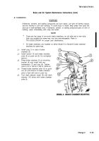
Release spring and service brake and check
that automatic slack adjuster’s installation
indicator (4) is within slot. If slack adjuster
fails this inspection, refer to para 11-5.1
(front) or para 11-6.1 (rear).
Remove cotter pin (5) and clevis pin (6).
Discard cotter pin (5). Check that yoke (7)
hole and slack adjuster (8) hole remain in
alinement. If brake chamber yoke (7)
retracts into the brake chamber, it fails
inspection and must be readjusted. Refer to
para 11-5.1 (front) or para 11-6.1 (rear).
Install clevis pin (6) and new cotter pin (5).
11-20
Change 2
Back to Top

