TM-9-2320-280-20-2 - Page 240 of 951
TM 9-2320-280-20-2
4-14
Change 3
Section II. STARTER AND STARTING CONTROL SYSTEM MAINTENANCE
4-6. STARTER AND STARTING CONTROL SYSTEM MAINTENANCE TASK SUMMARY
4-7. ROTARY SWITCH REPLACEMENT
TASK
PAGE
PARA.
PROCEDURES
NO.
4-7.
Rotary Switch Replacement
4-14
4-8.
Starter Replacement
4-16
4-9.
Circuit Breaker Replacement
4-20
This task covers:
a.
Removal
b. Installation
INITIAL SETUP:
NOTE
Prior to removal, tag leads and note position of lever for installation.
1.
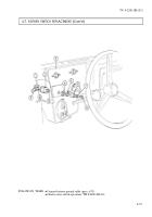
Remove screw (8), lockwasher (7), and switch lever (6) from switch shaft (9). Discard lockwasher (7).
2.
Remove nut (5) and lockwasher (4) from switch (2) and instrument panel (3). Discard lockwasher (4).
3.
Push switch (2) out of hole in panel (3).
4.
Disconnect three electrical leads 11A (1), 14A (10), and 29A (11) from switch (2) and remove switch (2).
1.
Connect three electrical leads 11A (1), 14A (10), and 29A (11) on switch (2).
2.
Install switch (2) into hole in panel (3).
3.
Install lockwasher (4) and nut (5) on switch (2).
4.
Place switch lever (6) on switch shaft (9) to indicate ENGINE STOP position.
5.
Secure lever (6) on switch shaft (9) with lockwasher (7) and screw (8).
b. Installation
a. Removal
Tools
General mechanic’s tool kit:
automotive (Appendix B, Item 1)
Materials/Parts
Lockwasher (Appendix G, Item 136)
Lockwasher (Appendix G, Item 162)
Manual References
TM 9-2320-280-10
TM 9-2320-280-24P
Equipment Condition
Battery ground cable disconnected
(para. 4-73).
Back to Top


