TM-9-2320-280-20-2 - Page 309 of 951
This task covers:
a. Removal
b. Installation
INITIAL SETUP:
Applicable Models
_______________
M997A2, M1025A2, M1035A2, M1043A2,
M1045A2, M1097A2
Tools
General mechanic’s tool kit:
automotive (Appendix B, Item 1)
Materials/Parts
Two lockwashers (Appendix G, Item 135)
Manual References
TM 9-2320-280-10
TM 9-2320-280-24P
Equipment Condition
• Engine access cover removed (para. 10-15).
• Battery ground cable disconnected (para. 4-73).
• Hood raised and secured (TM 9-2320-280-10).
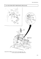
4-44. FAN CUT-OFF SWITCH REPLACEMENT (4L80-E)
1.
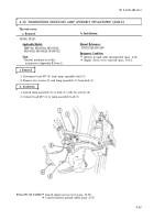
Slide rod (1) forward and disconnect from fuel injection pump (2).
2.
Remove rod (1) from switch (11).
3.
Disconnect harness leads 315A/315B (10) from leads 315 (9).
4.
Remove two nuts (13), lockwashers (12), washers (8), capscrews (7), washers (8), and switch (11)
from bracket (5). Discard lockwashers (12).
5.
Remove two capscrews (3), leads (4), and bracket (5) from engine (6).
TM 9-2320-280-20-2
4-70
Change 3
NOTE
Prior to removal, tag leads for installation.
b. Installation
a. Removal
1.
Install switch (11) on bracket (5) with two washers (8), capscrews (7), washers (8), lockwashers (12),
and nuts (13). Do not tighten nuts (13).
2.
Slide rod (1) forward and connect to fuel injection pump (2).
3.
Install rod (1) on switch (11).
4.
Install bracket (5) and two leads (4) on engine (6) with capscrews (3).
5.
Position rod (1) at wide open throttle and position switch (11) to close. Tighten nuts (13).
6.
Connect harness leads 315A/315B (10) to leads 315 (9).
Back to Top


