TM-9-2320-280-20-2 - Page 34 of 951
TM 9-2320-280-20-2
3-9. CRANKCASE DEPRESSION REGULATOR (CDR) VALVE AND BRACKET
MAINTENANCE
This task covers:
a. Testing
c. Cleaning and Inspection
b. Removal
d. Installation
INITIAL SETUP:
Tools
Manual References
General mechanic’s tool kit:
TM 9-2320-280-10
automotive (Appendix B, Item 1)
TM 9-2320-280-24P
Test Equipment
Equipment Condition
Manometer, U-tube
Hood raised and secured (TM 9-2320-280-10).
(Appendix B, Section IV, Item L)
Engine access cover removed (para. 10-15).
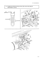
a. Testing
1. Remove engine oil dipstick from oil dipstick tube (para. 3-2).
2. Install manometer in dipstick tube.
3. Connect STE/ICE-R unit to DCA connector.
NOTE
To read manometer, add amount the water column travels above
zero to the amount the water column travels below zero.
4. Start engine and let idle; record water pressure. Pressure should be zero inches of water or a slight
vacuum.
5. Increase engine speed to 2,000 rpm; record water pressure. Pressure should be 2-5 inches.
6. If pressures are not within specifications listed in steps 4 and 5, replace CDR valve (9) and repeat
test.
7. Install oil dipstick in engine oil dipstick tube (para. 3-2).
NOTE
CDR valves on vehicles equipped with deep water fording kit
contain two additional vent lines.
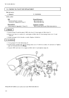
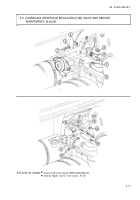
1. Loosen clamp (7) and discomect CDR valve oil fill tube hose (8) from CDR valve (9).
2. Loosen clamp (6) on CDR valve intake manifold hose (5).
3. Remove two screws (1), washers (2), CDR valve (9), and heater control cable clamp (3) horn CDR
valve bracket (4).
4. Remove two nuts (10) from CDR valve bracket (4) and two intake manifold studs (11).
5. Remove two nuts (13) and CDR valve bracket (4) from two valve cover studs (12).
3-14
Back to Top

