TM-9-2320-280-20-2 - Page 708 of 951
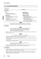
This task covers:
a. Removal
c. Installation
b. Inspection
INITIAL SETUP:
Tools
General mechanic’s tool kit:
automotive (Appendix B, Item 1)
Materials/Parts
Four lockwashers (Appendix G, Item 134)
Two lockwashers (Appendix G, Item 178)
Cotter pin (Appendix G, Item 12)
Cotter pin (Appendix G, Item 21)
Four gaskets (Appendix G, Item 59)
Two locknuts (Appendix G, Item 70)
Sealing compound (Appendix C, Item 45)
Grease (Appendix C, Item 22)
Personnel Required
One mechanic
One assistant
Manual References
TM-9-2320-280-10
TM 9-2320-280-24P
Equipment Condition
Wheels chocked and parking brake released
(TM 9-2320-280-10)
TM 9-2320-280-20-2
7-4
Change 3
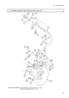
7-3. PARKING BRAKE CALIPER AND ROTOR MAINTENANCE
NOTE
The following procedure applies to vehicles with serial numbers
USBL Eff. 1 through 44824.
1.
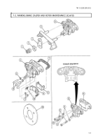
Remove four capscrews (15) and lockwashers (14) from rear propeller shaft (16) and parking brake
rotor (13). Disconnect rear propeller shaft (16) and remove rotor (13). Discard lockwashers (14).
2.
Remove cotter pin (17) from slotted nut (19), and loosen slotted nut (19). Discard cotter pin (17).
3.
Remove cotter pin (24), washer (23), spring (21), clevis pin (3), and clevis (22) from cam (20).
Remove spring (21) from pin post (18). Discard cotter pin (24).
4.
Remove two locknuts (11), washers (6), capscrews (5), washers (6), and clamp (4) from parking
brake cable (7) and plate and guide pin assembly (8). Discard locknuts (11).
5.
Remove two capscrews (1) and lockwashers (2) from plate and guide pin assembly (8) and caliper
mounting bracket (9). Discard lockwashers (2).
6.
Slide plate and guide pin assembly (8) towards front of vehicle until pins (10) come out of
bracket (9).
7.
Remove plate and guide pin assembly (8) and caliper assembly (12).
a. Removal
Back to Top

