TM-9-2320-280-20-2 - Page 714 of 951
This task covers:
a. Removal
b. Installation
INITIAL SETUP:
Tools
General mechanic’s tool kit:
automotive (Appendix B, Item 1)
Materials/Parts
Two assembled locknuts
(Appendix G, Item 131)
Five locknuts (Appendix G, Item 71)
Cotter pin (Appendix G, Item 12)
Personnel Required
One mechanic
One assistant
Manual References
TM-9-2320-280-10
TM 9-2320-280-24P
Equipment Condition
• Wheels chocked and parking brake released
(TM 9-2320-280-10).
• Parking brake switch removed (para. 4-19).
TM 9-2320-280-20-2
7-10
Change 3
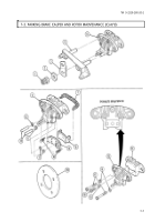
7-4. PARKING BRAKE LEVER REPLACEMENT
1.
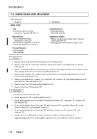
Remove clip (1) and open boot (2) to allow access to clevis pin (4).
2.
Remove cotter pin (7), washer (6), and clevis pin (4) from clevis (5) and bellcrank (3). Discard
cotter pin (7).
3.
Remove assembled locknut (9), wiring harness clamp (10), assembled locknut (9) and capscrew (19)
from parking brake lever (8). Discard assembled locknut (9).
4.
Remove three locknuts (11), washers (12), and capscrews (17) from parking brake lever (8) and
body (20). Discard locknuts (11).
5.
Remove two locknuts (16), washers (15), capscrews (13), washers (14), and parking brake lever (8)
from body (20). Discard locknuts (16).
6.
Remove upper boot (18) from parking brake lever (8).
7.
Remove lower boot (2) from body (20).
1.
Install lower boot (2) on body (20).
2.
Install upper boot (18) on parking brake lever (8).
3.
Install parking brake lever (8) on body (20) with two washers (14), capscrews (13), washers (15),
and locknuts (16).
4.
Secure parking brake lever (8) on body (20) with capscrew (19), assembled locknut (9), wiring
harness clamp (10), and assembled locknut (9).
5.
Secure parking brake lever (8) on body (20) with three capscrews (17), washers (12), and
locknuts (11).
6.
Install clevis (5) on bellcrank (3) with clevis pin (4), washer (6), and cotter pin (7).
7.
Apply parking brake lever (8) and tighten capscrews (13), (17), and (19) to 8 lb-ft (11 N
•
m).
b. Installation
a. Removal
Back to Top


