TM-9-2320-280-20-2 - Page 876 of 951
8-74.2
Change 3
INITIAL SETUP:
Applicable Models
All M1123 and “A2” series vehicles
Tools
General mechanic’s tool kit:
automotive (Appendix B, Item 1)
Maintenance and repair shop equipment:
automotive (Appendix B, Item 2)
Special Tools
Pulley installer (Appendix B, Item 137)
Materials/Parts
O-ring (Appendix G, Item 208)
Lockwasher (Appendix G, Item 190)
Manual References
TM 9-2320-280-10
TM 9-2320-280-24P
Equipment Condition
• Hood raised and secured (TM 9-2320-280-10).
• Serpentine drivebelt removed (para. 3-83).
8-24.1.
POWER STEERING PUMP AND PULLEY REPLACEMENT (6.5L)
This task covers:
a. Removal
b. Installation
TM 9-2320-280-20-2
a. Removal
CAUTION
Cover or plug all hoses and connections immediately after
disconnection to prevent contamination. Remove all plugs prior to
connection.
1.
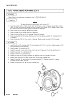
Loosen two clamps (2) and disconnect return lines (1) and high-pressure line (5) from power
steering pump (3). Remove O-ring (4) from high-pressure line (5). Discard O-ring (4).
2.
Remove nut (7), clamp (8), and wiring harness (6) from power steering pump (3).
3.
Remove nut (15), lockwasher (14), capscrew (9), washer (10), and idler pulley (11) from bracket (12).
Discard lockwasher (14).
4.
Remove two capscrews (17), capscrew (18), and power steering pump (3) from mounting bracket (16).
5.
Remove capscrew (19), washer (20), and power steering pulley (21) from power steering pump (3).
NOTE
Ensure flat surface of pulley is facing out and is flush with pump shaft.
1.
Using pulley installer, install pulley (21) on power steering pump (3).
2.
Secure pulley (21) to power steering pump (3) with washer (20) and capscrew (19). Tighten
capscrew (19) to 37 lb-ft (50 N
•
m).
3.
Install power steering pump (3) on mounting bracket (16) with capscrew (18) and two capscrews (17).
4.
Install idler pulley (11) on bracket (12) with washer (10), capscrew (9), lockwasher (14), and nut (15).
5.
Install O-ring (4) on high-pressure line (5) and install high-pressure line (5) on power steering
pump (3).
6.
Install two return lines (1) on power steering pump (3) and tighten clamps (2).
7.
Install wiring harness (6) and clamp (8) on power steering pump (3) with nut (7).
CAUTION
Serpentine belt failure (abnormal wear and belt dislodgement)
can be caused by misalignment of pulleys, improper installation,
or foreign objects introduced into belt path. For pulley alignment
procedures, refer to para. 3-83.
b. Installation
Back to Top


