TM-9-2320-280-20-3 - Page 221 of 1168
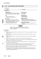
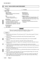
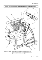
10-108. 9,000 LB ELECTRIC WINCH REPLACEMENT
This task covers:
a. Removal
b.
Installation
a. Removal
1.
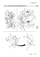
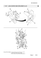
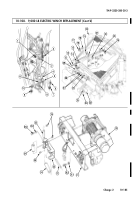
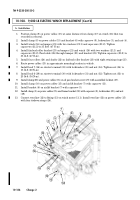
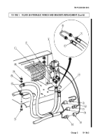
Remove nut (9) and lockwasher (10) and disconnect lead 7 (11) from starter terminal (8). Discard
lockwasher (10).
2.
Remove nut (7) and lockwasher (6) and disconnect lead 6 (4) from starter terminal (5). Discard
lockwasher (6).
3.
Remove assembled locknut (1) and clamp (3) from oil pan bracket screw (2). Discard assembled
locknut (1).
4.
Remove two capscrews (18), clamp (23), and bracket (19) from airlift bracket (20).
5.
Remove nut (12), lockwasher (13), capscrew (15), and clamp (14) from frame bracket (29). Discard
lockwasher (13).
6.
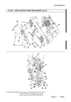
Disconnect vent line (24) from fitting (25) on winch motor (23.1) and remove four tiedown
straps (26) and vent line (24) from power cables (27). Pull cables (27) to front of vehicle and discard
tiedown straps (26).
7.
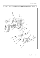
Remove four retaining rings (35), two shafts (32), and rollers (34) from fairlead roller bracket (33).
Pull cable (38) through bumper (31).
8.
Remove two capscrews (31.2), washers (31.1), and fairlead roller bracket (33) from bumper (31) and
winch (30).
9.
Remove two capscrews (31.2) and washers (31.1) from winch (30) and front bumper (31). Lower and
remove winch (30) and power cables (27) from vehicle.
10.
Measure length of power cables (27) from clamp (28) on winch (30) to clamp (21) on bracket (19)
and record. Remove nut (17), lockwasher (16), capscrew (22), clamp (21), and bracket (19) from
power cables (27). Discard lockwasher (16).
INITIAL SETUP:
Applicable Models
M997A2, M1025A2, M1035A2, M1043A2,
M1045A2, M1097A2
Tools
General mechanic’s tool kit:
automotive (Appendix B, Item 1)
Materials/Parts
Two lockwashers (Appendix G, Item 164)
Lockwasher (Appendix G, Item 137)
Lockwasher (Appendix G, Item 194)
Four tiedown straps (Appendix G, Item 308)
Assembled locknut (Appendix G, Item 130)
Personnel Required
One mechanic
One assistant
Manual References
TM 9-2320-280-10
TM 9-2320-280-24P
Equipment Condition
• Battery ground cables disconnected (para. 4-73).
• Hood raised and secured (TM 9-2320-280-10).
• Engine right splash shield removed (para. 10-20).
General Safety Instructions
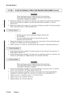
Winch must be supported during removal and
installation.
10-184
Change 2
WARNING
Winch must be supported during removal and installation. Failure to support
winch may result in injury to personnel or damage to equipment.
TM 9-2320-280-20-3
Back to Top

