TM-9-2320-280-20-3 - Page 354 of 1168
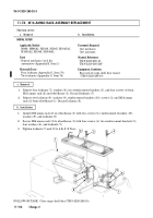
11-73. ELEVATION AND DEPRESSION STOP ASSEMBLY MAINTENANCE
This task covers:
a. Disassembly
b. Assembly
a. Disassembly
1.
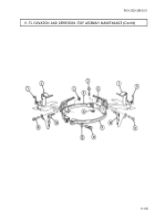
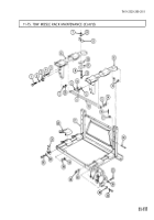
Remove retaining ring (3), clevis pin (15), cable end of pin assembly (14), and return spring (1) from
upward stop strap (4). Discard retaining ring (3).
2.
Remove pin assembly (14) and upward stop bracket (2) from upward stop strap (4).
3.
Remove retaining ring (6), clevis pin (9), cable end of pin assembly (10), and return spring (8) from
downward stop strap (11). Discard retaining ring (6).
4.
Remove pin assembly (10) and downward stop bracket (7) from downward stop strap (11).
5.
Remove retaining ring (16), clevis pin (5), socket head screw (12), and washer (13) from stop
straps (4) and (11). Discard retaining ring (16).
INITIAL SETUP:
Applicable Models
M966, M966A1, M1036, M1045, M1045A1,
M1045A2, M1046, M1046A1
Tools
General mechanic’s tool kit:
automotive (Appendix B, Item 1)
Materials/Parts
Three retaining rings (Appendix G, Item 235)
Manual References
TM 9-2320-280-24P
General Safety Instructions
Note position of downward stop and upward stop
for assembly.
b. Assembly
1.
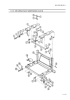
Install stop straps (4) and (11) together with clevis pin (5), retaining ring (16), washer (13), and
socket head screw (12).
2.
Install downward stop bracket (7) on downward stop strap (11) with pin assembly (10) through
upper holes of downward stop bracket (7) and downward stop strap (11).
3.
Install return spring (8), downward stop bracket (7), and cable end of pin assembly (10) on
downward stop strap (11) with clevis pin (9) and retaining ring (6).
4.
Install upward stop bracket (2) on upward stop strap (4) with pin assembly (14) through upper
holes of upward stop bracket (2) and upward stop strap (4).
5.
Install return spring (1), upward stop bracket (2), and cable end of pin assembly (14) on upward
stop strap (4) with clevis pin (15) and retaining ring (3).
WARNING
Note position of elevation and depression downward stop and
upward stop for assembly. Injury to personnel and/or damage to
equipment will result if stops are not properly assembled.
TM 9-2320-280-20-3
11-104
Change 2
Back to Top

