TM-9-2320-280-34 - Page 374 of 1258
TM 9-2320-280-34
Change 1
6 - 4 4 . 5
6-5.1. 200 AMPERE DUAL VOLTAGE ALTERNATOR (12447109) TESTING AND REPAIR (Cont'd)
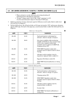
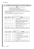
CONNECT
DISCONNECT
DIAGNOSIS
AMPS RISE
AMPS FALL
Alternator OK. See note. Replace regulator
only if low AMPS (40-59)/low VOLTS (21-25)
are indicated in table 6-D and/or table 6-E.
NO CHANGE
NO CHANGE
Alternator must be repaired. Refer to static
testing, task c.
Table 6-G. Regulator Bypass Test.
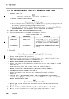
NOT E
• Perform this test only when instructed from tables 6-D and 6-E.
• Use jumper wire rated for 15 amps.
12.
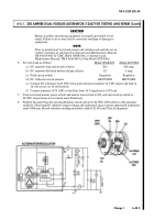
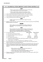
Disconnect alternator connector from regulator. With alternator spinning, use jumper wire and
short pin A to ground momentarily. Record results.
13.
Amperage should rise within ± 10 percent of rated value with jumper wire connected, and fall with
jumper disconnected. Refer to table 6-G for diagnosis.
14.
Turn test stand master power switch and load switch to OFF.
15.
Disconnect jumper wires from terminals on test stand and alternator.
16.
Remove belt from test stand pulley and alternator pulley. Remove alternator from test stand.
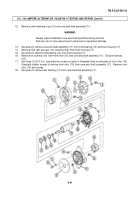
ALTERNATOR
28 VDC
14 VDC
SPEED
OUTPUT CURRENT
OUTPUT CURRENT
(RPM)
±5 AMP
MINIMUM AMP
*0
26
4
33
1,200
20
17
30
7
**37
0
*6
40
50
40
1,500
60
30
74
16
**90
0
*0
20
2,000
8
40
90
42
105
27
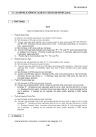
ALTERNATOR
28 VDC
14 VDC
SPEED
OUTPUT CURRENT
OUTPUT CURRENT
(RPM)
±5 AMP
MINIMUM AMP
2000
120
12
132
0
8
23
110
50
3000
130
30
150
10
160
8q
*0
8
5000
8
10
to
140
40
8000
165
25
180
10
190
0
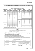
Table 6-F. Alternator Speed and Current Tracking.
*Dependent on ammeter location in test circuit.
**Minimum acceptable current with no load on 28 VDC system.
Back to Top

