TM-9-2320-280-34 - Page 916 of 1258
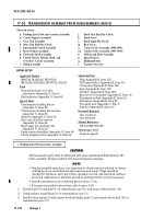
1 7 - 3 0 . TRANSMISSION ASSEMBLY FROM SUBASSEMBLIES (4L80-E)
INITIAL SETUP:
Applicable Models
M997A2, M1025A2, M1035A2,
M1043A2, M1045A2, M1097A2, M1123
Tools
General mechanic's tool kit:
automotive (Appendix G, Item 1)
Dial indicator (Appendix G, Item 95)
Special Tools
Transmission holding fixture
(Appendix G, Item 29)
Transmission holding fixture base
(Appendix G, Item 30)
Adapter (Appendix G, Item 41)
Gear unit installer/remover
(Appendix G, Item 44)
Band apply pin checking tool
(Appendix G, Item 53)
Pump remover/installer (Appendix G, Item 43)
Clutch alignment tool (Appendix G, Item 38)
Materials/Parts
Plug (Appendix E, Item 135)
Oil Pump Gasket (Appendix E, Item 35)
O-ring seal (Appendix E, Item 11 8 )
Seal (Appendix E, Item 173)
Oil filter (Appendix E, Item 122)
Rear servo cover gasket (Appendix E, Item 31)
Transmission fluid (Appendix B, Item 24)
Petrolatum (Appendix B, Item 38)
Two guide pins (Appendix C, Fig. 2)
Sealant (Appendix B, Item 43)
Personnel Required
One mechanic
One assistant
Manual References
TM 9-23320-280-24P
Maintenance Level
General support
TM 9-2320-280-34
1 7 - 1 3 0
Change 1
This task covers:
a.
Parking Lock Pawl and Actuator Assembly
b.
Center Support Assembly
c.
Gear Unit Assembly
d.
Rear Unit End Play Check
e.
Intermediate Clutch Assembly
f.
Direct Clutch Assembly
g.
Forward Clutch Assembly
h.
Fourth Clutch, Turbine Shaft, and
Overdrive Carrier Assembly
i.
Pump Assembly
j.
Front Unit End Play Check
k.
Front Servo
l.
Band Apply Pin Check
m.
Rear Servo
n.
Control Valve Assembly (1995-1996)
n.1.
Control Valve Assembly (1997-1998)
o.
Oil Pan and Filter Assembly
p.
Speed Sensors
q.
Holding Fixture
r.
Torque Converter
CAUTION
All transmission parts must be lubricated with clean transmission fluid (Dexron
®
I I I )
before assembly. Foreign material will cause transmission damage.
NOT E
• During assembly operations, it is important to closely inspect each unit to ensure
nothing has been overlooked during inspection and repair. Plugs should be
checked for tightness, parts kept clean, openings covered, and machined surfaces
protected. Application of lubricant should be performed from covered containers.
• Install transmission case in holding fixture (para. 17-14).
• For general assembly instructions, refer to para. 2-16.
1.
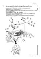
Install shaft (14) and pawl (1) in transmission case (11) and secure with retainer (12).
2.
Using sealant, install plug (13) in transmission case (11).
3.
Install return spring (2) with square hook end under pawl (1) and round end on stud (15) in
transmission case (11).
a. Parking Lock Pawl Actuator Assembly
Back to Top

