TM-9-2320-283-13-P - Page 13 of 400
TM 9-2320-283-13&P
TABLE OF CONTENTS - CONTINUED
Page No.
WP Sequence No.
v
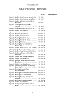
Figure 40. Drilling Mounting Holes for Front
Modulator . . . . . . . . . . . . . . . . . . . . . . . . . . .
WP 0018-27
Figure 41. Installing Front Modulators . . . . . . . . . . . . . .
WP 0018-27
Figure 42. Assembling Front Bulkhead . . . . . . . . . . . . .
WP 0018-28
Figure 43. Installing Bulkhead Bracket and
Connecting Tubes . . . . . . . . . . . . . . . . . . . . .
WP 0018-28
Figure 44. Disconnecting Tubing from Relay Valve . . .
WP 0018-29
Figure 45. Connecting Tube to Relay Valve and
Right-Rear Modulator . . . . . . . . . . . . . . . . . .
WP 0018-29
Figure 46. Connecting Tube to Relay Valve and
Left-Rear Modulator . . . . . . . . . . . . . . . . . . .
WP 0018-30
Figure 47. Assembling Right-Rear Bulkhead . . . . . . . . .
WP 0018-30
Figure 48. Installing Right-Rear Bulkhead . . . . . . . . . . .
WP 0018-31
Figure 49. Installing Left-Forward Bulkhead . . . . . . . . .
WP 0018-32
Figure 50. Installing Left-Forward Bulkhead . . . . . . . . .
WP 0018-33
Figure 51. Connecting Tube to Right-Rear Modulator . .
WP 0018-34
Figure 52. Connecting Tube to Left-Rear Modulator . . .
WP 0018-34
Figure 53. Installing Forward-Rear Axle Bulkhead . . . .
WP 0018-35
Figure 54. Disconnecting Tubes from Primary
Reservoir . . . . . . . . . . . . . . . . . . . . . . . . . . . .
WP 0018-36
Figure 55. Removing Primary Reservoir . . . . . . . . . . . .
WP 0018-37
Figure 56. Removing Fittings from Primary Reservoir .
WP 0018-37
Figure 57. Installing Fittings on Primary Reservoir . . . .
WP 0018-38
Figure 58. Installing 5/8 Tube on Brake Treadle Valve .
WP 0018-39
Figure 59. Installing Primary Reservoir . . . . . . . . . . . . .
WP 0018-40
Figure 60. Connecting Tubes to Primary Reservoir . . . .
WP 0018-41
Figure 61. Replacing Tube and Quick Release Valves . .
WP 0018-41
Figure 62. Replacing Tube Between Double Check and
Protection Valves . . . . . . . . . . . . . . . . . . . . . .
WP 0018-42
Figure 63. Installing Quick-Release Valve on
Protection Valve . . . . . . . . . . . . . . . . . . . . . . .
WP 0018-43
Figure 64. Removing Brake Chambers from
Rear-Rear Axle . . . . . . . . . . . . . . . . . . . . . . .
WP 0018-44
Figure 65. Shortening Pushrod and Installing Clevis . . .
WP 0018-45
Figure 66. Installing Elbows on Spring Brake Chamber
WP 0018-45
Figure 67. Installing Spring Brake Chambers . . . . . . . .
WP 0018-46
Figure 68. Installing Tube on Quick-Release Valve . . . .
WP 0018-47
Figure 69. Installing Mountable Tee on
Right Frame Rail . . . . . . . . . . . . . . . . . . . . . .
WP 0018-47
Back to Top

