TM-9-2320-283-20-2 - Page 202 of 852
TM 9-2320-283-20-2
ELECTRICAL SYSTEM.
3-97.
BLACKOUT TAILLAMP ASSEMBLY REPLACEMENT (Continued)
LOCATION/ITEM
ACTION
REMARKS
NOTE
Blackout taillamp assembly replacement procedures
are
the
same for
both sides.
This procedure covers
replacement of the left side blackout taillamp assembly.
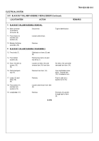
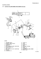
A. BLACKOUT TAILLAMP REMOVAL.
1.
Six screws (13).
Loosen.
Six items (13) cannot be
removed from item (14).
2.
Door (14).
Remove.
3.
Preformed pack-
Remove.
Use small blade screw-
ing (15).
driver.
Discard item
(15) if cracked o- torn.
4.
Stoplamp (16).
Remove.
Push in and turn a
quarter turn to the
left.
5.
Taillamp (12).
Remove.
Push in and turn a
quarter turn to the
left.
B. BLACKOUT TAILLAMP INSTALLATION.
6.
Stoplamp (12).
Install.
Push in and turn a
quarter turn to the
right.
7.
Taillamp (16).
Install.
Push in and turn a
quarter turn to the
right.
8.
Preformed pack-
Install in item (14).
ing (15).
9.
Door (14) with six
Align and install to item
screws (13).
(9).
Tighten six items (13).
3-574
Back to Top


