TM-9-2320-283-20-2 - Page 552 of 852
TM 9-2320-283-20-2
BRAKE SYSTEM.
3-158.
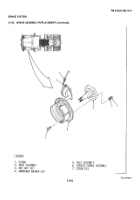
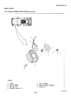
BRAKE ASSEMBLY REPLACEMENT (Continued)
LOCATION/ITEM
ACTION
REMARKS
NOTE
Replacement of the six brake assem-
blies is similar.
Left front is shown.
A. REMOVAL.
1.
Hose assembly (2).
Remove from item (1).
2.
Eight screws (7),
Remove from item (6).
washers (4), and
nuts (3).
3.
Brake assembly (6).
Remove from item (5).
Assistant helps
mechanic.
NOTE
Only do steps 4 and 5 to replace brake
assembly with a new one.
4.
Brake chamber.
Remove.
Refer to paragraphs
3-164 and 3-165.
5.
Slack adjuster.
Remove.
Refer to paragraph
3-157.
B. INSTALLATION.
6
Brake assembly (6).
Put in place on item (5).
Assistant helps
mechanic.
7.
Eight screws (7),
Secure item (6) to item (5).
Torque between 90 and
washers (4), and
100 lb.-ft.
nuts (3).
8.
Hose assembly (2).
Install on item (1).
3-924
Back to Top


