TM-9-2320-283-20-2 - Page 608 of 852
TM 9-2320-283-20-2
BRAKE SYSTEM.
3-168.
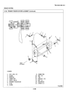
SUPPLY RESERVOIR REPLACEMENT (Continued).
LOCATION/ITEM
ACTION
REMARKS
B.
INSTALLATION.
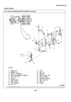
11.
Drain valve (7).
Remove from item (3).
Refer to paragraph
3-192.
12.
Elbow (19), male
Remove from item (3).
Refer to paragraph 3-188
run tee (17),
for item (15) removal.
reducer bushing
(16), safety
valve (15), and
male street tee
(14).
NOTE
Check air lines and fittings for leaks, cracks, and damaged threads.
Replace if necessary.
Be sure air lines
are connected to
the
proper reservoir port when reconnecting.
13.
Drain valve (7).
Coat threads with liquid
Refer to paragraph 3-192
thread sealant and install.
for installation.
14.
Quick disconnect
Coat threads with liquid
Refer to paragraph 3-188
coupler (4), elbow
thread sealant and install.
for item (15) installa-
(6), elbow (24),
tion.
male run tee (17),
reducer bushing
(16), safety valve
(15), and male
street tee (14).
15.
Two lower brackets
Move into position and aline
(2).
with lower mounting holes
in items (13) and item (9).
16.
Nut (10) and nut
Install on two lower items
(12).
(2) and tighten.
3-980
Back to Top


