TM-9-2320-283-34-1 - Page 14 of 624
TM 9-2320-283-34-1
EQUIPMENT DESCRIPTION AND DATA.
1-7.
EQUIPMENT CHARACTERISTICS, CAPABILITIES, AND FEATURES (Continued).
d.
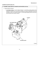
Alternator-Rectifier.
The alternator-rectifier consists of three basic subassemblies.
These subassemblies are
described in 1 through 3 below:
1.
Alternator.
The alternator is a self-load limiting device featuring p fully adjustable, built-in solid-state
voltage regulator.
The rated output of the alternator is 85 amperes at 14 volts dc nominal and has a maximum speed of
8,000 rpm.
Six silicon diodes mounted in heat sinks convert alternating current into direct current.
A capacitor
connected between the heat sinks assists in suppressing transient voltage spikes which could possibly injure the diodes.
The brushes and voltage regulator are located in a waterproof housing and may be removed for replacement or
inspection without dismantling the entire alternator.
The regulator is also equipped with transient voltage protection and
will withstand instantaneous opening of the charging circuit under full load conditions.
2.
Transformer Assembly.
The transformer assembly consists of a 3-phase transformer to obtain electrical
isolation from the alternator, and a 3-phase, full wave rectifier to provide dc output.
It is energized from the ac terminals
of the alternator to which it is connected by 3 leads.
The transformer assembly replaces the conventional series parallel
switch and is used to provide a source of power for charging the cranking batteries on 12-volt vehicles equipped with 24-
volt cranking motors.
The system batteries are charged by the transformer-rectifier unit.
1-3
Back to Top

