TM-9-2320-283-34-1 - Page 19 of 624
TM 9-2320-283-34-1
EQUIPMENT DESCRIPTION AND DATA
1-7.
EQUIPMENT CHARACTERISTICS, CAPABILITIES, AND FEATURES (Continued).
f.
Transmission (Continued).
1.
Torque Converter (Continued).
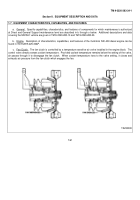
Oil thrown into the turbine flows to the stator vanes.
The stator vanes change the direction of oil flow and
directs the oil to pump in a direction that assists the rotation of the pump.
It is the redirection of the oil in a
manner to assist the pump that enables the torque converter to multiply input torque.
Greatest torque
multiplication occurs when the turbine is stalled and the pump is rotating at its highest speed.
Torque
multiplication decreases as the turbine rotates and gains speed.
When turbine speed approaches the speed of
the pump, oil flowing to the stator begins striking the backs of the stator vanes.
This rotates the stator in the
same direction as the turbine and pump.
At this point, torque multiplication stops and the converter becomes,
in effect, a fluid coupling.
2.
Lockup Clutch.
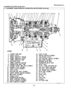
The lockup clutch consists of a piston, a clutch, and a backplate.
These are located
inside the flex disk and ring gear (flywheel).
The piston and backplate rotate with the converter pump.
The
clutch plate is located between the piston and backplate and is splined to the converter turbine.
When sufficient rotational speed is achieved, hydraulic pressure compresses the lockup clutch plate between
the piston and backplate, locking all three together.
Thus, the converter pump and turbine are locked together,
and provide a direct drive from the engine.
As rotational speed decreases, the lockup clutch is released.
1-8
Back to Top

