TM-9-2320-283-34-1 - Page 203 of 624
TM 9-2320-283-34-1
ELECTRICAL SYSTEM.
3-21.
ALTERNATOR AND RECTIFIER REPAIR (Continued).
LOCATION/ITEM
ACTION
REMARKS
E.
ASSEMBLY (Continued).
35.
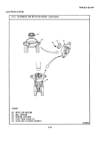
Holder (20)
b.
Insert item (13) into
A suitable pin can be
(continued)
outer hole in item (20)
made from a paper clip.
and compress item (13).
While holding item (13),
insert suitable pin
through hole in rear of
housing so that spring is
held in compressed
position.
c.
Install the remaining item
(13) in the same manner,
by pushing pin farther
into housing.
36.
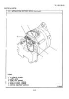
Regulator assembly
a.
Install item (19) onto
(16)
item (16) and aline holes.
b.
While holding item (16)
Tighten item (15).
in one hand, attach item
(42) to item (16) and in-
stall items (14) and (15).
c.
Attach item (29) to item
Tighten item (15).
(16) and install items
(14) and (15).
37.
Holder (20).
a.
Attach blue regulator lead
to stud on item (20) by
slipping under head of
nut.
Tighten nut.
b.
Install item (16) onto
Be sure that the red
item (20) and install
and black leads are
four items (18).
Do not
properly routed through
tighten screws.
their slots in the
regulator housing.
c.
Remove pin from rear of
item (20), and tighten
four items (18).
d.
Attach black diode lead to
item (20) and tighten item
(2).
3-150
Back to Top


