TM-9-2320-283-34-1 - Page 209 of 624
TM 9-2320-283-34-1
ELECTRICAL SYSTEM.
3-21.
ALTERNATOR AND RECTIFIER REPAIR (Continued).
LOCATION/ITEM
ACTION
REMARKS
F.
BENCH TESTING.
43.
Alternator
a.
Connect positive and
assembly (71).
negative output leads to
test stand.
b.
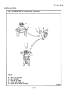
Connect jumper wire (A) to
diode trio terminal (B)
and quickly touch positive
output terminal (C) with
other end of jumper wire
(A) to restore the remain-
ing magnetism.
c. On test stand, run item
(71) to 580-620 rpm.
d.
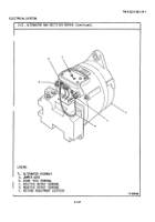
Adjust voltage output to
14 vdc at location (E) of
item (71).
e.
Vary load on item (71)
between 1 and 85 amps,
and check that the output
matches the load.
f.
Now adjust output to 28
vdc, at location (E) of
item (71).
g.
Vary load on item (71)
between 1 and 15 amps,
and check that the output
matches the load.
h.
If output does not match
load repeat steps 43c
through g.
NOTE
Follow-on maintenance action required:
Install alternator (TM 9-2320-
283-20).
3-156
Back to Top


