TM-9-2320-285-24-1 - Page 431 of 987
TM 9-2320-285-24-1
2-35.
WIRING HARNESS MAINTENANCE (CONT)
c.
Instrument Panel Harnesses (cont).
(3)
Right Panel Harness (cont).
STEP
LOCATION
ITEM
ACTION
REMARKS
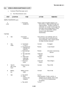
INSPECTION/REPAIR (cont)
2
d.
Right panel
Inspect
Repair if insulation frayed
(cont)
harness (5)
or conductor broken.
Wrap
electrical tape over frayed
insulation.
If broken
conductor is accessible,
cut a length of same gage
wire and splice using in-
sulated splice connector;
if wire is not accessible,
replace harness (notify
direct support maintenance)
TESTING
3
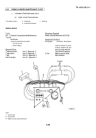
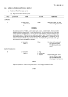
Right
a.
Right panel
Test
Use multimeter set to X1 ohms
corner
harness (5)
continuity
range (refer to electrical
panel,
system wiring schematic);
underside
refer to step (2) above for
repair of broken conductor
b.
Connectors
Connect
As tagged
(2 thru 4)
c.
Connector (1)
Connect
Para 2-35d
4
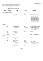
Cab tilt
Cab
Lower
To normal operating
position
pump
5
Battery
Battery ground
Connect
Para 2-34a
box
cable
6
Cab
a.
Key switch
Turn on
b.
Lights,
Check
If lights, controls, or
controls, and
operation
indicators do not operate,
indicators
refer to para 2-17 thru
2-23 for troubleshooting
procedures
c.
Key switch
Turn off
2-408
Back to Top

