TM-9-2320-328-13-P-1 - Page 72 of 1318
TM 9-2320-328-13&P-1
0004-10
DRAFT
0004
Change 1
-
-
-
-
-
-
-
-
-
-
-
-
-
-
-
-
-
-
-
-
-
-
-
-
-
-
-
-
-
-
-
-
-
-
-
-
-
-
-
-
-
-
-
-
-
-
-
-
-
-
-
-
-
-
-
-
-
-
-
-
-
-
-
-
-
-
-
-
-
-
-
-
-
-
-
-
HWT0182A
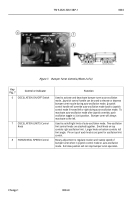
Figure 9. Pump Operator’s Panel - Left.
Key
Fig. 9
Control or Indicator
Function
1
PUMP COOLER Switch
Pull out and push right to open pump cooler valve and activate
pump cooler system.
Push left to close pump cooler valve.
2
PUMP COOLER Indicator Light
Illuminates when pump cooler valve is open.
3
FOAM SYSTEM Switch
Pull out and push right to open foam valve and discharge foam into
water line.
Push left to close foam valve.
4
FOAM SYSTEM Indicator Light
Illuminates when foam valve is open.
5
Headset Jack
Used to communicate with personnel using headset system.
6
PANEL LIGHTS Switch
Illuminates pump operator’s panel when switch is ON.
7
FOAM FLUSH Switch
Pull out and push right to open foam flush valve and activate foam
flush system.
Push left to close foam flush valve.
8
FOAM FLUSH Indicator Light
Illuminates when foam flush valve is open.
9
Driver Main Inlet Primer Button
Push and hold to activate primer pump.
Used to prime water
pump.
Release button to deactivate primer pump.
10
Manual Pressure Control Knob
Used when manual mode is selected to control PTO driven
hydraulic pump output pressure.
Back to Top


