TM-9-2320-328-13-P-2 - Page 679 of 1390
TM 9-2320-328-13&P-2
0205-5
DRAFT
0205
Change 1
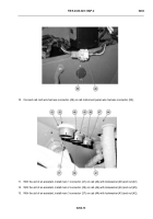
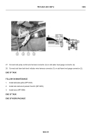
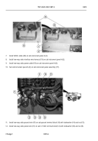
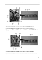
18. Remove three grommets (25), (26), and (27) from cab instrument panel A (2).
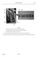
NOTE
All four louvers are removed the same way.
Driver side outer louver shown.
19. Remove screw (28), spring (29), and louver assembly (30) from cab instrument panel A (2).
END OF TASK
PANEL A INSTALLATION
-
-
-
-
-
-
-
-
-
-
-
-
-
-
-
-
-
-
-
-
-
-
-
-
-
-
-
-
-
-
-
-
-
-
-
-
-
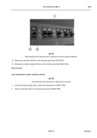
NOTE
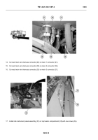
All four louvers are installed the same.
Driver side outer louver shown.
1.
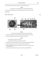
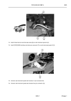
Install louver assembly (30) on cab instrument panel A (2) with spring (29) and screw (28).
2.
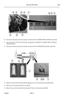
Install three grommets (27), (26), and (25) on cab instrument panel A (2).
NOTE
•
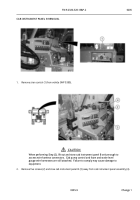
Route harnesses as noted prior to removal.
•
Install cable ties, split loom, and cushion clips as required.
3.
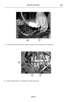
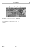
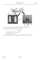
Install front and rear lower warning flasher unit (24) on cab instrument panel A (2) (WP 0196).
4.
Install side warning flasher unit (23) on cab instrument panel A (2) (WP 0196).
5.
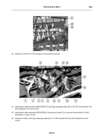
Install check for open compartment door when light is on flasher unit (22) on cab instrument
panel A (2) (WP 0196).
6.
Install upper rear warning flasher unit (21) on cab instrument panel A (2) (WP 0196).
.
.
.
.
.
.
.
.
.
.
.
.
.
.
.
.
.
.
.
.
.
.
.
.
.
.
.
.
.
.
.
.
.
HWT3478
Back to Top

