TM-9-2320-328-13-P-2 - Page 688 of 1390
TM 9-2320-328-13&P-2
0205-14
DRAFT
0205
Change 1
-
-
-
-
-
-
-
-
-
-
-
-
-
-
-
-
-
-
-
-
-
-
-
-
-
-
-
-
-
-
-
-
-
-
-
-
-
-
3.
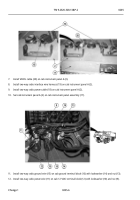
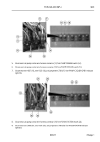
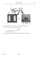
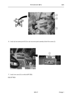
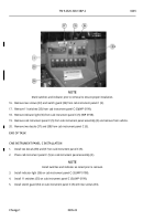
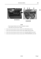
Install bracket (37) on cab instrument panel B (3) with two screws (36) and nuts (35).
4.
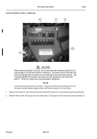
Place cab instrument panel B (3) in stow position on vehicle.
NOTE
•
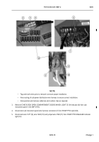
Route harnesses as noted prior to removal.
•
Install cable ties as required.
5.
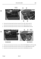
Install cab foam (33) and water (34) level gauges on cab instrument panel B (3) (WP 0200).
-
-
-
-
-
-
-
-
-
-
-
-
-
-
-
-
-
-
-
-
-
-
-
-
-
-
-
-
-
-
-
-
-
-
-
-
-
-
-
-
-
-
-
-
-
-
-
-
-
-
-
-
-
-
HWT2498A
Back to Top

