TM-9-2320-361-20 - Page 565 of 1207
TM 9-2320-361-20
7-20. SHOCK ABSORBER REPLACEMENT
This task covers:
a. Removal
b. Installation
INITIAL SETUP:
APPLICABLE MODELS
All
REFERENCES (TM)
TM 9-2320-361-10
TM 9-2320-361-20P
EQUIPMENT CONDITION
Parking brake set (TM 9-2320-361-10).
a. Removal
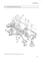
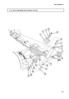
1. Remove jamnut (17), nut (16), retainer (15), and rubber bushing (14) from shock absorber piston
rod (10).
2. Push shock absorber piston rod (10) up through hole in plate (13) and remove upper rubber
bushing (12) and retainer (11).
3. Remove jamnut (5), nut (4), upper retainer (3), and rubber bushing (2) from upper rod (8).
4. Remove shock absorber (9), lower retainer (7), and rubber bushing (6) from of frame bracket (1).
b. Installation
1.
2.
3.
4.
5.
6.
7.
8.
Position retainer (7) and rubber bushing (6) on upper rod (8) of shock absorber (9). Ensure lip of
bushing (6) is facing up.
Position upper rod (8) through hole in frame bracket (1) and install rubber bushing (2), retainer (3),
and nut (4) on rod (8). Ensure lip of bushing (2) is in hole in frame bracket (1).
Tighten nut (4) until two rubber bushings (2) and (6) start to bulge.
Install jamnut (5) against nut (4).
Install retainer (11) and rubber bushing (12) on piston rod (10). Ensure lip of rubber bushing (12) is
facing down.
Pull piston rod (10) down through hole in plate (13) and install rubber bushing (14), retainer (15),
and nut (16). Ensure lip of bushing (14) is in hole of plate (13).
Tighten nut (16) until two rubber bushings (14) and (12) start to bulge.
Install jamnut (17) against nut (16).
7-46
Back to Top

