TM-9-2320-361-20 - Page 851 of 1207
TM 9-2320-361-20
12-45. WATER TANK DISCHARGE TUBE AND VALVE REPLACEMENT (M50A2)
This task covers:
a. Discharge Tube Removal
c. Discharge Valve Installation
b. Discharge Valve Removal
d. Discharge Tube Installation
INITIAL SETUP:
APPLICABLE MODELS
EQUIPMENT CONDITION
M50A2
Parking brake set (TM 9-2320-361-10).
MATERIALS/PARTS
Water tanks drained (TM 9-2320-361-10).
Four gaskets
GENERAL SAFETY INSTRUCTIONS
Eighteen locknuts
Wear gloves when handling cable.
REFERENCES (TM)
TM 9-2320-361-10
TM 9-2320-361-20P
WARNIN G
Wear leather gloves when handling cable. Do not let cable run
through hands. Broken or rusty wires can cause injury to personnel.
a. Discharge Tube Removal
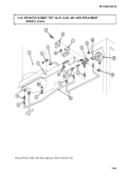
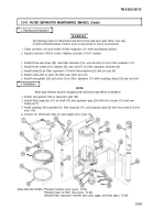
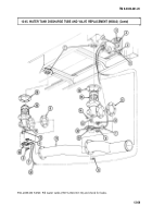
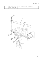
1. Remove two nuts (5), screws (4), and coupling (3). Slide gasket (2) back on tube (11).
2. Remove twelve locknuts (14), screws (9), tube (11), gasket (2), and two gaskets (6) from two
discharge valves (15). Discard gaskets (2) and (6) and locknuts (14).
b. Discharge Valve Removal
NOTE
Both discharge valves are removed and installed the same way.
1. Remove nut (7) from clip (8) and remove cable (12) and thimble (10) from lever (13).
2. Remove six locknuts (17), discharge valve (15), and gasket (16) from bottom of tank (1). Discard
locknuts (17) and gasket (16).
c. Discharge Valve Installation
1. Install new gasket (16) and discharge valve (15) on bottom of tank (1) with six new locknuts (17).
2. Install cable (12) and thimble (10) on lever (13) with clip (8) and nut (7).
d. Discharge Tube Installation
1. Install new gasket (2) on tube (11).
2. Install two new gaskets (6) and tube (11) on two discharge valves (15) with twelve screws (9) and
new locknuts (14).
3. Slide gasket (2) to end of tube (11) and install coupling (3) with two screws (4) and nuts (5).
12-68
Back to Top

