TM-9-2320-361-20 - Page 853 of 1207
TM 9-2320-361-20
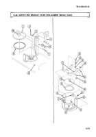
12-46. WATER TANK DISCHARGE TUBE AND VALVE REPLACEMENT (M50A3)
This task covers:
a. Discharge Tube Cover Removal
d. Discharge Valves Installation
b. Discharge Tube Removal
e. Discharge Tube Installation
c. Discharge Valves Removal
f. Discharge Tube Cover Installation
INITIAL SETUP:
APPLICABLE MODELS
REFERENCES (TM)
M50A3
TM 9-2320-361-10
MATERIALS/PARTS
TM 9-2320-361-20P
Five gaskets
EQUIPMENT CONDITION
Ten locknuts
Parking brake set (TM 9-2320-361-10).
Water tanks drained (TM 9-2320-361-10).
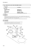
a. Discharge Tube Cover Removal
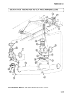
1. Remove fifty-two screws (3) from discharge tube cover (2).
2. Slide discharge tube cover (2) left to access discharge valves (9) and discharge tube (19).
b. Discharge Tube Removal
1. Remove four locknuts (11), two holders (10), U-bolts (12), and cables (13) and (22) from two
discharge valves (9). Discard locknuts (11).
2. Remove two cables (13) and (22) from two guides (14) and (20).
3. Remove two nuts (7), screws (6), coupling (5) and gasket (4) from discharge tube (19). Discard
gasket (4).
4. Remove four nuts (15), guides (14) and (20), four screws (18), two couplings (17), two gaskets (16),
and discharge tube (19) from two discharge valves (9). Discard gaskets (16).
c. Discharge Valves Removal
NOTE
Both discharge valves are replaced the same way.
Remove six locknuts (21), discharge valve (9), and gasket (8) from bottom of tank (1). Discard gasket (8)
and locknuts (21).
d. Discharge Valves Installation
Install new gasket (8) and discharge valve (9) on bottom of tank (1) with six new locknuts (21).
e. Discharge Tube Installation
1. Install discharge tube (19) on two discharge valves (9) with two new gaskets (16), two couplings (17),
four screws (18), and four nuts (15).
2. Install new gasket (4) and coupling (5) on discharge tube (19) with two screws (6) and nuts (7).
3. Install two cables (13) and (22) through guides (14) and (20).
4. Install two cables (13) and (22) on two discharge valves (9) with two U-bolts (12), holders (10), and
four new locknuts (11).
12-70
Back to Top

