TM-9-2320-361-24-1 - Page 1054 of 1176
TM 9-2320-361-24-1
0167 00
0167 00-6
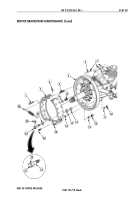
SERVICE BRAKESHOES MAINTENANCE (Contd)
INSTALLATION
1.
Mark ends of new or old anchor pins (23) with center punch indicating highest cam lobe position.
2.
Apply light coat of grease on backing plate (5) where brakeshoes (2) and (19) may rub.
NOTE
• Perform steps 3 and 4 if anchor pins and cams have been
removed.
• Final tightening of cam nuts and anchor pin nuts is done in
brakeshoe adjustment.
3.
Install felt washers (14), retainer washers (17), and anchor pins (23) on backing plate (5) with two
washers (13) and nuts (12). Do not tighten nuts (12).
4.
Install two adjusting pins (9), springs (15), and cams (16) on backing plate (5). Peen ends of two
adjusting pins (9) securely against cams (16) to hold in place.
5.
Turn anchor pins (23) so that center punch marks (21) are close together.
6.
Set cam (16) so that tip points down.
NOTE
Brakeshoes must be a matched set on both ends of axle.
7.
Install two brakeshoes (2) and (19) on anchor pins (23) against wheel cylinder pushrods (8) and
against backing plate (5) with two retainer washers (18), new lower (short) guide pins (20),
washers (11), and nuts (10).
8.
Install two anti-rattle springs (4) and washers (3) between two brakeshoes (2) and (19) and
backing plate (5) with two upper (long) guide pins (1), washers (6), and nuts (7).
9.
Tighten upper guide pin nuts (7) 19–24 lb-ft (26–33 N
•
m) and lower guide pin nuts (10)
11–16 lb-ft (15–22 N
•
m).
10.
Install two retainer washers (25) and new retaining clips (24) on anchor pins (23). Squeeze
retaining clips (24) into slots (22) of anchor pins (23).
NOTE
Ensure brakeshoes are still positioned against wheel cylinder
pushrods after brakeshoe return spring is installed.
11.
Install brakeshoe return spring (26) on two brakeshoes (2) and (19).
12.
Replace hub and brakedrums (WP 0187 00).
13.
Perform service brake adjustment (WP 01
6
8 00).
14.
Connect battery ground cable (WP 0126 00).
15.
Release parking brake and remove wheel chocks (TM 9-2320-361-10).
Back to Top


